
Water-Lubricated
Oil-Free Compressors
Single-stage compression. Water replaces oil in the chamber entirely. ISO 8573-1 Class 0 by mechanical design — not by filtration. 7.5 kW to 320 kW. Two series: fixed-speed CM/B and permanent magnet VFD CM/PV.
What Sets Water-Lubricated Compression Apart
In a conventional oil-injected screw compressor, oil lubricates, seals, and cools — creating an inseparable contamination pathway into the air stream. In a dry oil-free machine, rotors run metal-to-metal in forced clearance, requiring two compression stages, 10,000–20,000 RPM operation to minimise leakage, and generating discharge temperatures of 180–300 °C. The resulting mechanical stress places extreme load on bearings designed for a fraction of the required service life.
EPG Canada’s water-lubricated oil-free compressors inject demineralised water directly into the single-stage compression chamber. Water’s specific heat capacity (4.18 kJ/kg·K) — roughly four times that of mineral oil — holds discharge temperature at or below 50 °C. The water film seals rotor clearances without high-speed operation or two-stage compression. Rotors run at motor speed (≤ 3,000 RPM), direct-coupled with no speed-increasing gearbox. Bearing load is a fraction of that in a dry oil-free machine — design life exceeds 25 years.
The compression chamber contains no oil — not by filtration, not by separation, but by mechanical fact. That is the basis for ISO 8573-1 Class 0 certification and TÜV Class 0 verification. The result is testable and reproducible because there is nothing to filter out.
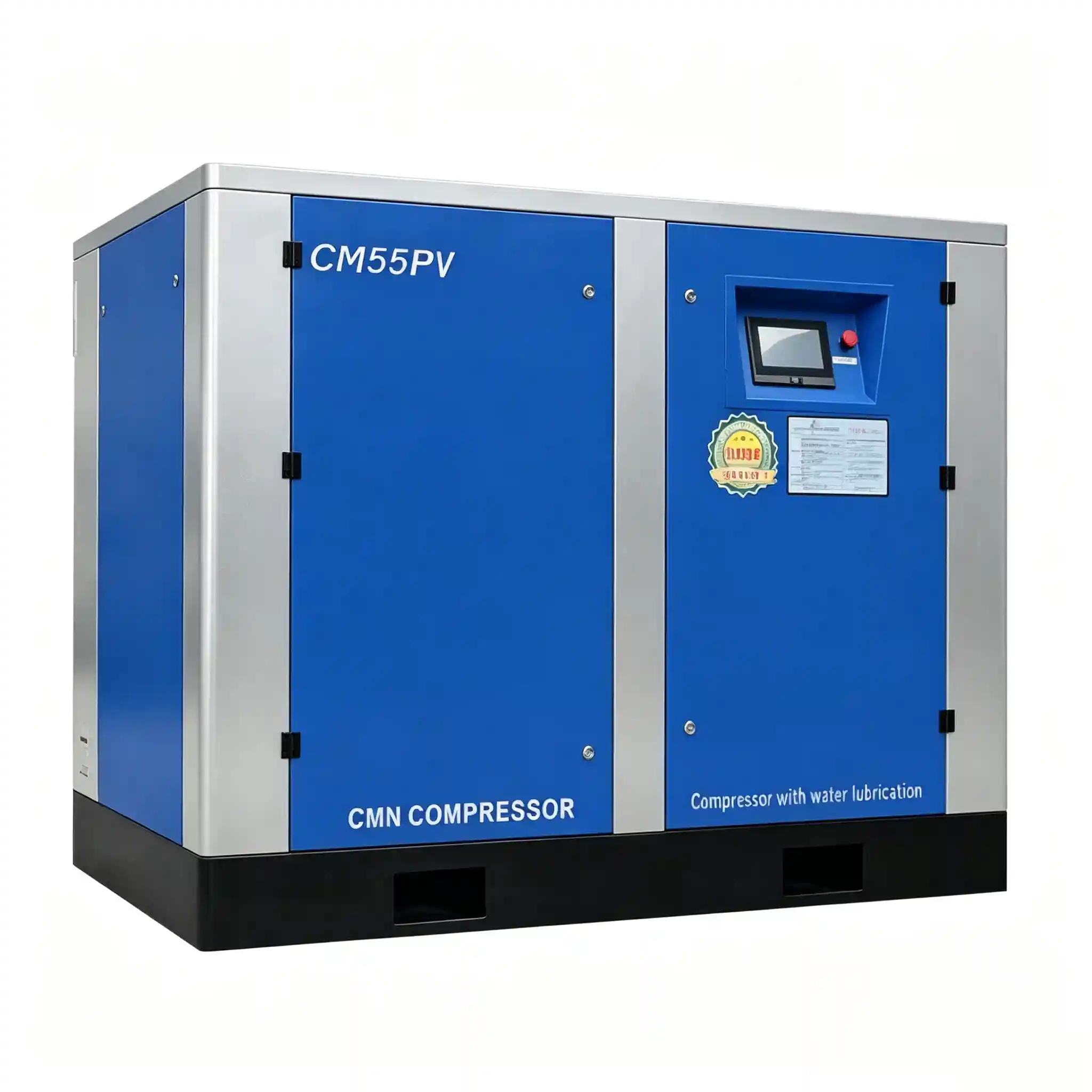
Engineering
Key Components — What’s Inside the Cabinet
Every component is designed as a system. Water and oil circuits are fully isolated. Every surface contacting compressed air is 316L stainless or inert polymer.
Stainless Steel Airend
Independently developed oil-free stainless steel airend (Patented). Features ultra-high volumetric efficiency and a patented seal-less design, providing a design lifespan of over 25 years.
Lubricating Water Filtration System
Pure stainless steel housing with premium original filter elements. The high-precision, multi-layer glass fiber design achieves 0.1μm filtration accuracy. Clean lubricating water significantly extends the main host's lifespan.
Full Stainless Steel Water Cooler
Utilizes a high-performance stainless steel plate heat exchanger with a multi-pass cooling structure. The greatly expanded cooling area ensures optimal heat dissipation, keeping the discharge temperature below 55°C.
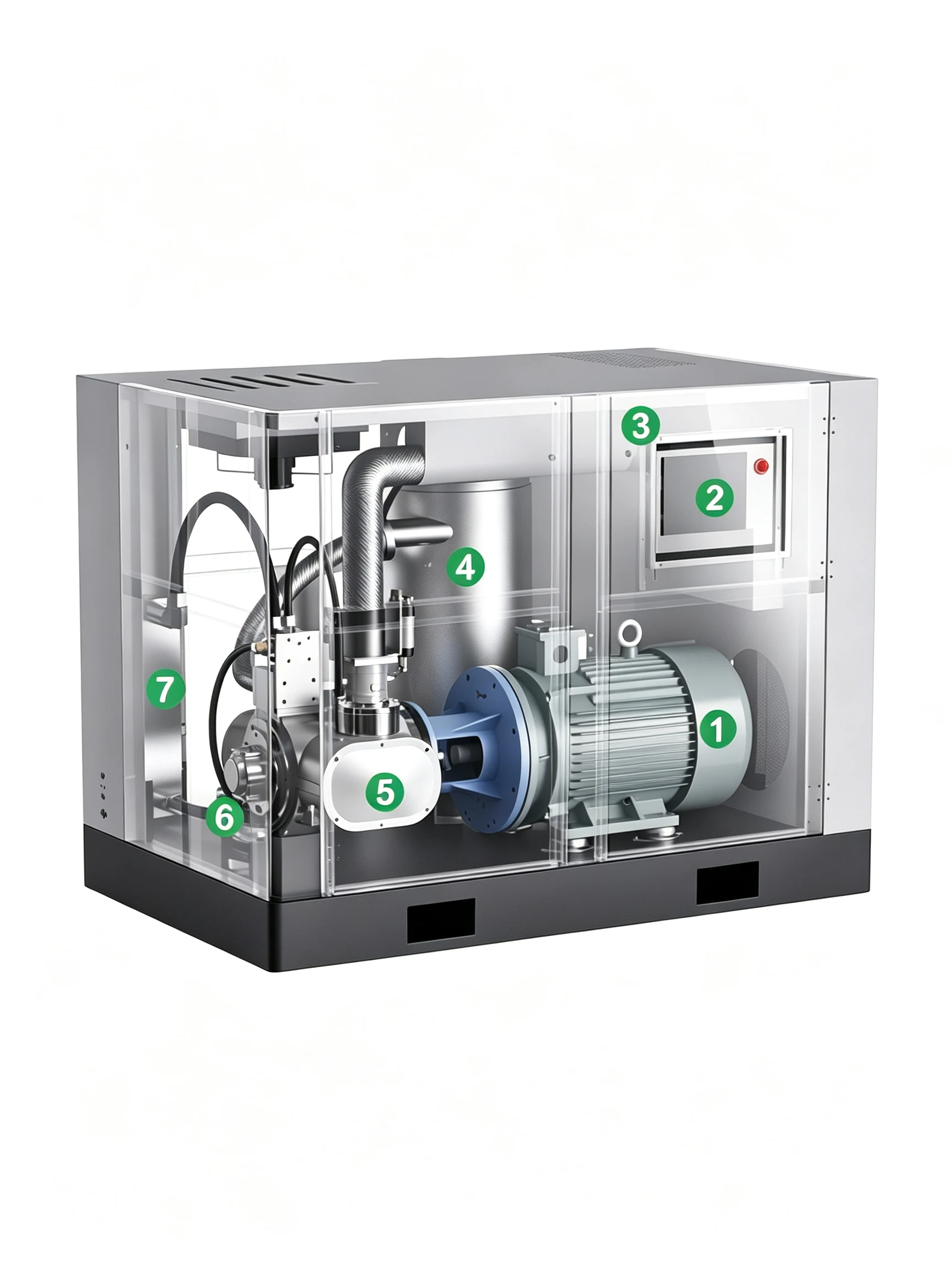
Permanent Magnet Motor
Premium customized motor using rare earth permanent magnet materials. Protection grade IP55, insulation class F, built-in SKF bearings. Efficiency is 3%-5% higher than similar products, ensuring 24/7 continuous operation. Customization available.
Intelligent Computer Control System
Advanced control and fault early warning capabilities. The user-friendly HMI displays all operational data. Features a robust RS485 remote control interface. An intelligent microcomputer regulates pressure precisely, maximizing equipment efficiency.
High-Efficiency Intake Valve
Patented high-efficiency intake valve ensuring 100% reliability. The integrated low-point air intake design improves compression efficiency, reduces noise, and extends air filter life. A modular openable enclosure enhances maintenance convenience.
Water-Air Separator Tank
Constructed from full stainless steel to prevent internal flaking. A streamlined internal baffle accelerates airflow up to 10m/s for thorough moisture separation. Water settles at the bottom while dry air discharges through a minimum pressure valve.
Product Series
Two Series — Same Platform, Different Drive Systems
Both share the identical water-lubricated 316L stainless air end, TÜV Class 0 certification, and core architecture. Select by demand profile and energy strategy.
Best fit: Stable demand (> 80% average utilisation). Star-delta or soft-start. Lower capital cost versus CM/PV. Models CM08B–CM160B available in both air-cooled & water-cooled; CM200B–CM320B water-cooled only.
View Full CM/B Product Page →| Model | MPa | FAD m³/min | FAD cfm | kW/HP | dB(A) | CW T/h | CW pipe | Outlet |
|---|---|---|---|---|---|---|---|---|
| CM08B(F) | 0.8 | 1.15 | 41 | 7.5/10 | 58 | 2 | DN25 | 1" |
| 1.0 | 1.02 | 36 | ||||||
| CM11B(F) | 0.8 | 1.55 | 55 | 11/15 | 58 | 2.5 | DN25 | 1" |
| 1.0 | 1.32 | 47 | ||||||
| 1.25 | 1.02 | 36 | ||||||
| CM15B(F) | 0.8 | 2.40 | 85 | 15/20 | 63 | 3.5 | DN25 | 1" |
| 1.0 | 2.12 | 75 | ||||||
| 1.25 | 1.61 | 57 | ||||||
| CM18B(F) | 0.8 | 3.10 | 109 | 18.5/25 | 65 | 4 | DN25 | 1" |
| 1.0 | 2.62 | 93 | ||||||
| 1.25 | 2.13 | 75 | ||||||
| CM22B(F) | 0.8 | 3.50 | 124 | 22/30 | 65 | 5 | DN25 | 1" |
| 1.0 | 3.13 | 111 | ||||||
| 1.25 | 2.61 | 92 | ||||||
| CM30B(F) | 0.8 | 5.00 | 177 | 30/40 | 66 | 7 | DN40 | 1½" |
| 1.0 | 4.20 | 148 | ||||||
| 1.25 | 3.18 | 112 | ||||||
| CM37B(F) | 0.8 | 6.10 | 215 | 37/50 | 67 | 9 | DN40 | 1½" |
| 1.0 | 5.22 | 184 | ||||||
| 1.25 | 4.81 | 170 | ||||||
| CM45B(F) | 0.8 | 7.80 | 275 | 45/60 | 68 | 10 | DN40 | 2" |
| 1.0 | 6.13 | 216 | ||||||
| 1.25 | 5.65 | 200 | ||||||
| CM55B(F) | 0.8 | 9.60 | 339 | 55/75 | 70 | 12 | DN40 | 2" |
| 1.0 | 8.60 | 304 | ||||||
| 1.25 | 7.42 | 262 | ||||||
| CM75B(F) | 0.8 | 12.90 | 455 | 75/100 | 73 | 18 | DN40 | 2" |
| 1.0 | 11.42 | 403 | ||||||
| 1.25 | 9.83 | 347 | ||||||
| CM90B(F) | 0.8 | 16.30 | 576 | 90/125 | 73 | 20 | DN40 | 2½" |
| 1.0 | 14.52 | 513 | ||||||
| 1.25 | 12.30 | 434 | ||||||
| CM110B(F) | 0.8 | 19.40 | 685 | 110/150 | 78 | 24 | DN40 | 2½" |
| 1.0 | 16.90 | 597 | ||||||
| 1.25 | 15.10 | 533 | ||||||
| CM132B | 0.8 | 22.21 | 784 | 132/180 | 78 | 30 | DN50 | 2½" |
| 1.0 | 20.38 | 720 | ||||||
| 1.25 | 18.29 | 646 | ||||||
| CM160B(F) | 0.8 | 28.85 | 1019 | 160/220 | 78 | 35 | DN80 | DN100 |
| 1.0 | 24.52 | 866 | ||||||
| 1.25 | 22.17 | 783 | ||||||
| CM200B | 0.8 | 36.63 | 1293 | 200/270 | 78 | 43 | DN80 | DN100 |
| 1.0 | 32.70 | 1155 | ||||||
| 1.25 | 27.72 | 979 | ||||||
| CM250B | 0.8 | 42.88 | 1514 | 250/340 | 78 | 53 | DN80 | DN100 |
| 1.0 | 39.00 | 1377 | ||||||
| 1.25 | 34.64 | 1223 | ||||||
| CM320B | 0.8 | 59.10 | 2087 | 320/430 | 80 | 60 | DN100 | DN125 |
| 1.0 | 53.50 | 1889 | ||||||
| 1.25 | 48.25 | 1704 |
FAD per ISO 1217 Annex C. CW = cooling water quantity at inlet 32 °C. F suffix = air-cooled; base model = water-cooled.
IPM motor + VFD. Speed adjusts continuously 40–100% of rated to match demand — no load/unload cycling. CM132PV, CM200PV, CM250PV, CM320PV are water-cooled only.
View Full CM/PV Product Page →| Model | MPa | FAD range m³/min | FAD range cfm | kW/HP | dB(A) | CW T/h | CW pipe | Outlet |
|---|---|---|---|---|---|---|---|---|
| CM08PV(F) | 0.8 | 0.45~1.15 | 16~41 | 7.5/10 | 58 | 2 | DN25 | 1" |
| 1.0 | 0.41~1.02 | 14~36 | ||||||
| CM11PV(F) | 0.8 | 0.62~1.55 | 22~55 | 11/15 | 58 | 2.5 | DN25 | 1" |
| 1.0 | 0.53~1.32 | 19~47 | ||||||
| 1.25 | 0.48~1.02 | 17~36 | ||||||
| CM15PV(F) | 0.8 | 0.96~2.40 | 34~85 | 15/20 | 63 | 3.5 | DN25 | 1" |
| 1.0 | 0.85~2.12 | 30~75 | ||||||
| 1.25 | 0.64~1.61 | 23~57 | ||||||
| CM18PV(F) | 0.8 | 1.24~3.10 | 44~109 | 18.5/25 | 65 | 4 | DN25 | 1" |
| 1.0 | 1.05~2.62 | 37~93 | ||||||
| 1.25 | 0.85~2.13 | 30~75 | ||||||
| CM22PV(F) | 0.8 | 1.40~3.50 | 49~124 | 22/30 | 65 | 5 | DN25 | 1" |
| 1.0 | 1.25~3.13 | 44~111 | ||||||
| 1.25 | 1.04~2.61 | 37~92 | ||||||
| CM30PV(F) | 0.8 | 2.00~5.00 | 71~177 | 30/40 | 66 | 7 | DN40 | 1½" |
| 1.0 | 1.68~4.20 | 59~148 | ||||||
| 1.25 | 1.52~3.18 | 54~112 | ||||||
| CM37PV(F) | 0.8 | 2.44~6.10 | 86~215 | 37/50 | 67 | 9 | DN40 | 1½" |
| 1.0 | 2.09~5.22 | 74~184 | ||||||
| 1.25 | 1.92~4.81 | 68~170 | ||||||
| CM45PV(F) | 0.8 | 3.12~7.80 | 110~275 | 45/60 | 68 | 10 | DN40 | 2" |
| 1.0 | 2.45~6.13 | 87~216 | ||||||
| 1.25 | 2.26~5.65 | 80~200 | ||||||
| CM55PV(F) | 0.8 | 3.84~9.60 | 136~339 | 55/75 | 70 | 12 | DN40 | 2" |
| 1.0 | 3.44~8.60 | 121~304 | ||||||
| 1.25 | 2.97~7.42 | 105~262 | ||||||
| CM75PV(F) | 0.8 | 5.16~12.90 | 182~456 | 75/100 | 73 | 18 | DN40 | 2" |
| 1.0 | 4.57~11.42 | 161~403 | ||||||
| 1.25 | 3.93~9.83 | 139~347 | ||||||
| CM90PV(F) | 0.8 | 6.52~16.30 | 230~576 | 90/125 | 73 | 20 | DN40 | 2½" |
| 1.0 | 5.81~14.52 | 205~513 | ||||||
| 1.25 | 4.92~12.30 | 174~434 | ||||||
| CM110PV(F) | 0.8 | 7.76~19.40 | 274~685 | 110/150 | 78 | 24 | DN40 | 2½" |
| 1.0 | 6.76~16.90 | 239~597 | ||||||
| 1.25 | 6.04~15.10 | 213~533 | ||||||
| CM132PV | 0.8 | 8.88~22.21 | 314~784 | 132/180 | 78 | 30 | DN50 | 2½" |
| 1.0 | 8.15~20.38 | 288~720 | ||||||
| 1.25 | 7.31~18.29 | 258~646 | ||||||
| CM160PV(F) | 0.8 | 11.54~28.85 | 407~1019 | 160/220 | 78 | 35 | DN80 | DN100 |
| 1.0 | 9.81~24.52 | 346~866 | ||||||
| 1.25 | 8.87~22.17 | 313~783 | ||||||
| CM200PV | 0.8 | 14.65~36.63 | 517~1293 | 200/270 | 78 | 43 | DN80 | DN100 |
| 1.0 | 13.10~32.70 | 463~1155 | ||||||
| 1.25 | 11.09~27.72 | 392~979 | ||||||
| CM250PV | 0.8 | 17.15~42.88 | 606~1514 | 250/340 | 78 | 53 | DN80 | DN100 |
| 1.0 | 15.60~39.00 | 551~1377 | ||||||
| 1.25 | 13.87~34.64 | 490~1223 | ||||||
| CM320PV | 0.8 | 23.64~59.10 | 835~2087 | 320/430 | 80 | 60 | DN100 | DN125 |
| 1.0 | 21.40~53.50 | 756~1889 | ||||||
| 1.25 | 19.30~48.25 | 681~1704 |
FAD range = min speed → max speed at rated pressure. CM132PV, CM200PV, CM250PV, CM320PV: water-cooled only.
- Demand is stable — < 15% variation
- Average utilisation > 80% of rated
- Capital cost is the primary objective
- Simple commissioning is preferred
- Demand swings 15–60%+ between shifts
- Annual energy cost reduction matters
- Tight pressure control needed (±0.1 MPa)
- ESG / energy audit reporting required
Product Series
Industry Applications — Where Class 0 Is the Only Acceptable Standard
Both share the identical water-lubricated 316L stainless air end, TÜV Class 0 certification, and core architecture. Select by demand profile and energy strategy.
≤ 50 °C
Discharge Temperature
Dry oil-free: 180–300 °C. At 50 °C, every component operates at near-ambient temperature — bearing life, seal life, and energy consumption all benefit directly.
7 Bearings
vs 14 in Dry Oil-Free
Single-stage direct-coupled design at ≤ 3,000 RPM uses 7 bearings. Dry oil-free needs 14 at 10,000–20,000 RPM. Fewer parts, lower speed, longer life.
8.8 kW/h
Energy Saving at 55 kW
At 55 kW: CM series delivers 9.6 m³/min vs 8.5 m³/min from a two-stage dry oil-free machine — 12% more air from the same motor, 8.8 kW/h less power consumed.
25 Years
Design Service Life
No high-speed gear wear, no rotor coating fatigue, no cooler scaling from 200 °C exhaust. Dry machines typically need major overhaul before year 5–10.
100,000 h
Bearing Service Life
Balanced radial and axial forces from the symmetric single-screw star-wheel design. TÜV-verified bearing life: 100,000+ operating hours.
Product Series
Industry Applications — Where Class 0 Is the Only Acceptable Standard
Both share the identical water-lubricated 316L stainless air end, TÜV Class 0 certification, and core architecture. Select by demand profile and energy strategy.
Head-to-Head
Water-Lubricated vs Dry Oil-Free — The Technical Case
Both machine types achieve ISO 8573-1 Class 0 certification. The differences are in how that result is achieved and what the operational consequences are over a 10-year horizon.
| Parameter | ★ ADVANCEDWater-Lubricated (CM/B & CM/PV) | Dry Oil-Free (Two-Stage) |
|---|---|---|
| Compression stages | Single stage | Two stages required at 0.8 MPa |
| Discharge temperature | ≤ 50 °C | 180–300 °C |
| Rotor speed | ≤ 3,000 RPM (direct-coupled) | 10,000–20,000 RPM (speed-increasing gearbox) |
| Number of bearings | 7 | 14 |
| Bearing life | 100,000+ hours | Limited — unbalanced loads at high speed |
| Seal system | 2 groups (labyrinth, no contact) | 8 groups — seal failure = oil contamination |
| Rotor coating | None — 316L stainless | PTFE/Teflon — degrades, flakes into air stream, periodic recoating required |
| FAD at 55 kW / 0.8 MPa | 9.6 m³/min | 8.5 m³/min (–12%) |
| Annual maintenance (55 kW) | Air filter + water filter only | Lube oil, oil filter, seals, air filter, rotor recoating — escalates after year 3 |
| Discharge moisture load | 83 g/m³ at ≤ 50 °C outlet | 230 g/m³ at 90 °C post-cooled — 2.8× higher dryer load |
| Design service life | 25+ years | < 10 years before major rebuild |
| Fire/explosion risk | None — unit operates below 55 °C | Fire/explosion prevention required at 200 °C |
| Minimum available power | 7.5 kW | 37 kW (two-stage architecture requires minimum size) |
Product Series
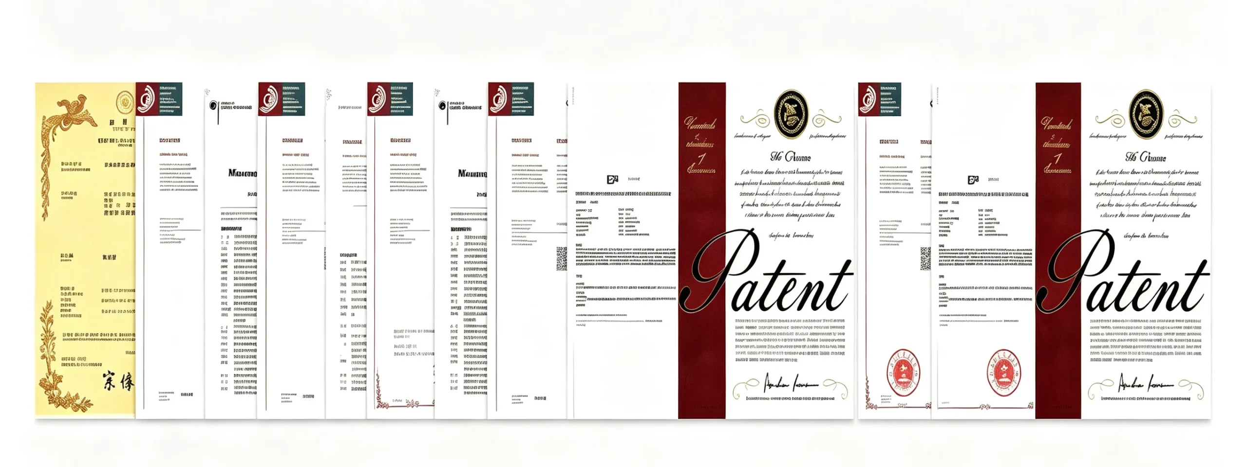
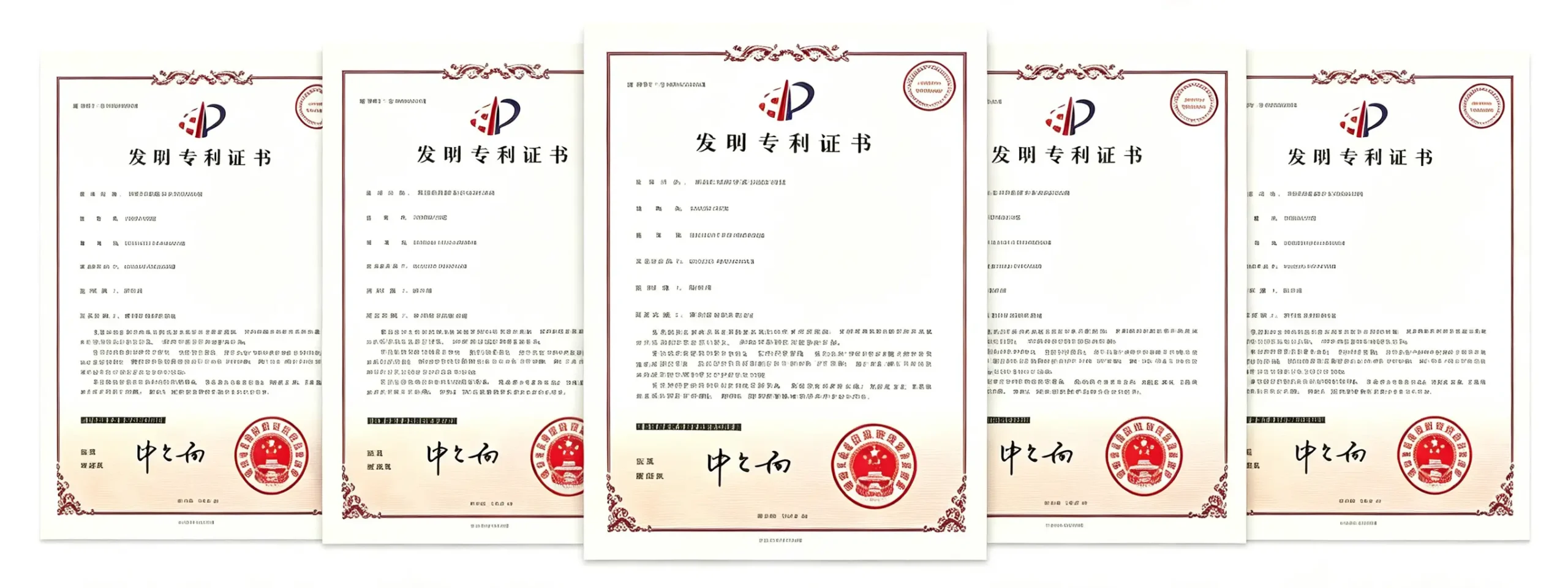
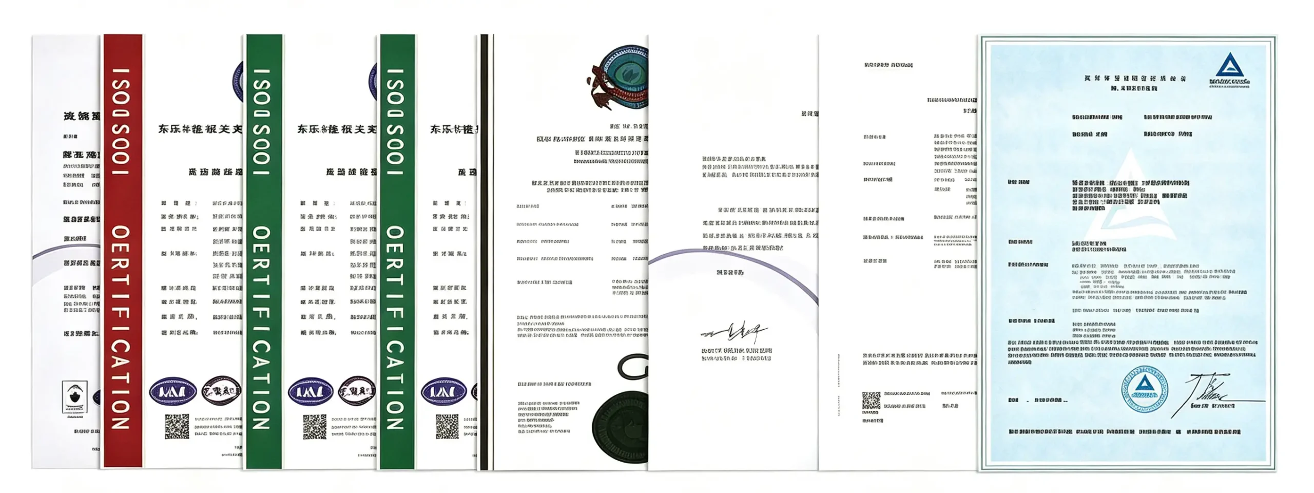
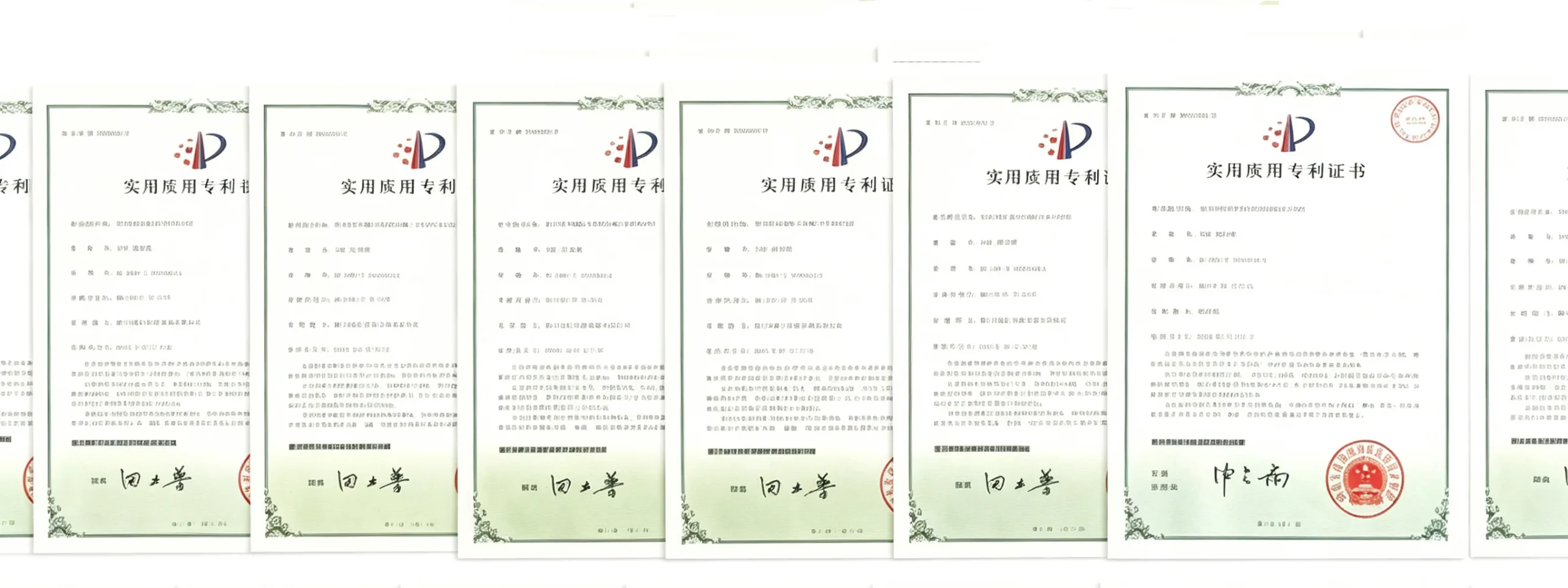
Certifications & Quality Standards
FAQ
Technical Questions — Answered Directly
Is water-lubricated truly Class 0, or does it still need downstream oil-removal filters?
Structurally Class 0 — there is no oil in the compression chamber by mechanical design. The labyrinth seal (no shaft seal contact) isolates the gearbox oil from the compression circuit. Only inlet air and demineralised water enter the compression chamber. This is the basis for TÜV Class 0 certification. Coalescing and activated-carbon filters are not required for oil-content compliance — a refrigerant or desiccant dryer for moisture control is still required, as with any compressor technology.
What does the water circuit require from the site?
The compression water loop uses demineralised or RO-purified water at conductivity ≤ 10 µS/cm at fill. The inline conductivity sensor raises an alarm at ≥ 200 µS/cm. Full drain and refill every 2,000 operating hours. Water-cooled models require a closed cooling water circuit at the T/h flow shown in specification tables, inlet ≤ 32 °C. The compression water and cooling water are completely separate circuits — they do not mix.
What markets and voltages does EPG Canada serve?
EPG Canada exports globally. Standard build: 380V / 3-phase / 50 Hz. 460V / 60 Hz (North America), 415V / 50 Hz (UK / Australia), and other voltages available at quotation stage. CE-marked for European market. ASME pressure vessel certification available on request for North American projects. Contact [email protected] with your site electrical specification.
How does output compare to a dry two-stage oil-free machine at the same motor power?
At 55 kW / 0.8 MPa: CM series delivers 9.6 m³/min; a typical two-stage dry oil-free machine delivers 8.5 m³/min — 12% more air from the same motor, and 8.8 kW/h less electricity consumed per hour. Single-stage water-lubricated compression achieves higher volumetric efficiency because the water film seals rotor clearances without requiring extreme speeds. Single-stage also eliminates intercooler pressure drop and inter-stage piping losses.
What GMP documentation is available for pharmaceutical validation?
Standard: CE declaration, TÜV Class 0 certificate, ISO 9001 certificate, factory test report, and 316L stainless material certificates for wetted components. Extended GMP package on request: surface roughness records, 3.1 material certs per EN 10204, IQ/OQ documentation templates (GAMP 5 aligned), and design FMEA extract. Advise requirement at order stage.