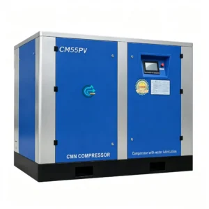
Description
CM/B Series Water Lubricated Oil-Free Screw Air Compressor
7.5 kW to 320 kW · 0.8–1.25 MPa · Class 0 certified · Air-cooled & water-cooled configurations
If you’ve ever had to explain to your quality team why an oil-carryover event shut down a filling line for eight hours, you already understand exactly why a water lubricated oil-free screw air compressor exists. Water replaces oil in the compression chamber entirely — there is no aerosol, no residual hydrocarbon, no carbon deposit risk, and no downstream activated-carbon filter to maintain. What you get out of the discharge flange is genuinely clean, dry, compressed air that meets ISO 8573-1 Class 0.
The CM/B series covers the full industrial range — from a compact 7.5 kW / 10 HP skid for smaller process lines up to a 320 kW / 430 HP station-grade machine delivering 53.50 m³/min at 1 MPa. Both air-cooled (CM-F suffix) and water-cooled variants are available across the entire lineup, which matters when you’re integrating into a building that already has a closed-loop cooling circuit but no adequate ventilation for heat rejection.
Water Lubricated Oil-Free Screw Air Compressor Technical Parameter Table — Full Series (CM08B to CM320B)
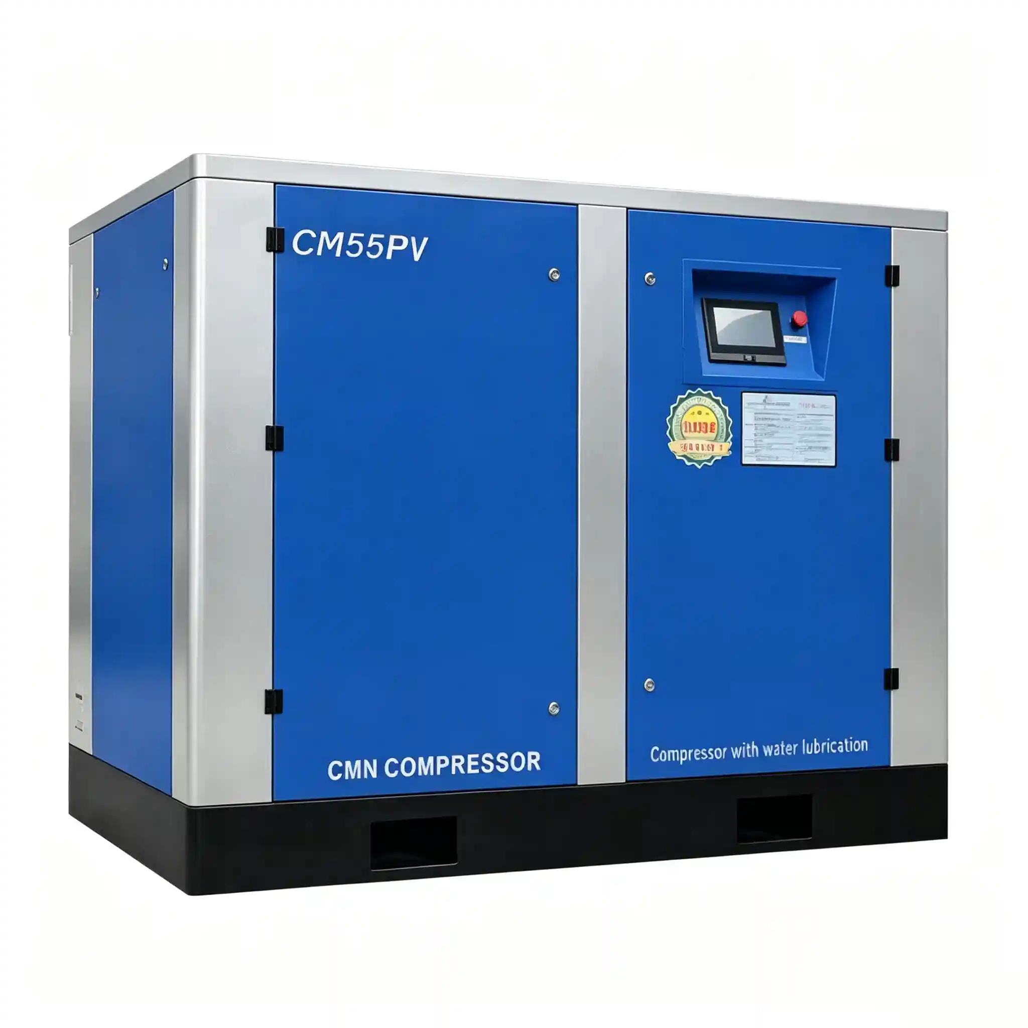
CM/B series full parameter table · 7.5 kW – 320 kW · 0.8 / 1.0 / 1.25 MPa · air-cooled & water-cooled
Why Water Instead of Oil? The Compression-Chamber Physics
In a conventional oil-injected screw compressor, oil does three jobs simultaneously: it lubricates the rotor surfaces, seals the meshing gap between male and female rotors, and absorbs the heat of compression. That works, but it creates an inseparable oil-contamination pathway into the air stream — regardless of how good your downstream separator and coalescing filter are, carryover is measured in ppm, not zero.
In the CM/B design, demineralised water is injected directly into the compression chamber. Water’s specific heat capacity (4.18 kJ/kg·K) is roughly four times that of mineral oil, so isothermal compression is much closer to reality — discharge air temperature typically stays under 45 °C above ambient. The water film also seals the rotor clearances with greater viscosity consistency across the compression cycle. Because the rotors run in water, not oil, there is no hydrocarbon contamination pathway by definition. The condensate that comes out the drain is simply slightly warm water — no special disposal.
The rotor bearings are isolated from the compression space by a double labyrinth seal arrangement. The gearbox oil circuit is a completely separate loop and never contacts the compression chamber. This is the mechanical basis for the Class 0 claim — not just filter performance, but actual physical separation.
Performance Highlights Worth Paying Attention To
CM/B Series Water Lubricated Oil-Free Screw Air Compressor — Representative Models at a Glance
Below is a condensed reference for the most commonly selected models. Full parameter tables for all 17 frame sizes are shown in the image above. FAD values are at rated working pressure; the F suffix (e.g. CM08BF) denotes an air-cooled (风冷) variant — water-cooled is the base model.
| Model | Pressure (MPa) | FAD (m³/min) | FAD (cfm) | Power (kW / HP) | Noise dB(A) | Cooling water T/h | Air outlet |
|---|---|---|---|---|---|---|---|
| CM08B(F) | 0.8 / 1.0 | 1.15 / 1.02 | 41 / 36 | 7.5 / 10 | 58 | 2 | 1″ |
| CM15B(F) | 0.8 / 1.0 / 1.25 | 2.40 / 2.12 / 1.61 | 85 / 75 / 57 | 15 / 20 | 63 | 3.5 | 1″ |
| CM30B(F) | 0.8 / 1.0 / 1.25 | 5.00 / 4.20 / 3.18 | 177 / 148 / 112 | 30 / 40 | 66 | 7 | 1-1/2″ |
| CM55B(F) | 0.8 / 1.0 / 1.25 | 9.60 / 8.60 / 7.42 | 339 / 304 / 262 | 55 / 75 | 70 | 12 | 2″ |
| CM90B(F) | 0.8 / 1.0 / 1.25 | 16.30 / 14.52 / 12.30 | 576 / 513 / 434 | 90 / 125 | 73 | 20 | 2-1/2″ |
| CM160B(F) | 0.8 / 1.0 / 1.25 | 28.85 / 24.52 / 22.17 | 1019 / 866 / 783 | 160 / 220 | 78 | 35 | DN100 |
| CM250B | 0.8 / 1.0 / 1.25 | 42.88 / 39.00 / 34.64 | 1514 / 1377 / 1223 | 250 / 340 | 78 | 53 | DN80 |
| CM320B | 0.8 / 1.0 / 1.25 | 59.10 / 53.50 / 48.25 | 2087 / 1889 / 1704 | 320 / 430 | 80 | 60 | DN125 |
All FAD values measured in accordance with ISO 1217 Annex C. Cooling water consumption based on inlet water temperature 32 °C. For complete specs on CM11B, CM18B, CM22B, CM37B, CM45B, CM75B, CM110B, CM132B, and CM200B, refer to the parameter table image above or contact our engineering team with your exact flow requirement and site conditions.
Air-Cooled (CM-F) vs Water-Cooled (CM-B): Which One Fits Your Site?
Both cooling configurations are available from CM08 to CM160. From CM200 upward, only water-cooled (base CM-B) is offered — the thermal load at those power levels makes forced-air rejection impractical without a very large plant footprint. Here’s the short version of what drives the selection decision on site:
Where an Oil-Free Screw Compressor Actually Earns Its Premium
The argument for an oil-free compressed air system versus an oil-injected machine plus downstream filtration comes down to one question: what is the cost of a single contamination event? In the industries below, the answer is usually “more than the price of this machine.”

FDA 21 CFR, EU GMP Annex 1, and ICH Q7 all require documented proof that compressed air in contact with product, packaging, or equipment has no oil content. “Oil-free at source” is the only defensible position in a regulatory inspection — downstream filtration can fail, clog, or be mis-specified. The CM/B series provides that position by design. A water lubricated oil-free screw air compressor for pharmaceutical industry deployment eliminates the validation burden of oil-removal filter systems entirely.
Sub-micron oil aerosols are lethal to lithography mask surfaces, wire-bond pads, and MEMS membranes. Fabs using Class 0 air from water-lubricated compressors avoid the cost and complexity of point-of-use oil monitors. The CM/B’s stable discharge temperature (≤ ambient + 45 °C) also makes it easier to maintain consistent dryer performance downstream.
Reaction vessel purging, pneumatic transport of catalyst powders, and polymer pellet conveying all demand air that won’t introduce hydrocarbon contamination into a tightly controlled chemistry environment. In plants handling oxidisers, the risk calculus for oil carryover also has a safety dimension, not just a quality one.
Air-jet looms and false-twist spinning machines require consistent, clean air at moderate pressure (0.5–0.7 MPa at the loom, so 0.8 MPa supply is standard). Oil-free supply prevents fibre contamination and eliminates the maintenance overhead of oil separators and filter elements that clog with textile dust.

Engineering Design — What’s Actually Inside the Cabinet
The following points are worth checking when you’re comparing this against competitor Class 0 air compressor offerings — because the marketing will all say “100% oil-free” and the differences show up in the mechanical specification, not the brochure.
- Rotor material & coating: Male and female rotors are manufactured from stainless steel (316L grade contact surfaces on compression chamber). Corrosion resistance in the water environment is structural, not applied — no coatings that can delaminate.
- Bearings: Thrust and radial bearings are located outside the compression space in a separate, sealed gear-oil-lubricated cavity. No water enters the bearing housing; no oil enters the compression chamber. The double labyrinth seal between the two cavities is the critical component — verify the seal material specification (PTFE-impregnated carbon) when comparing.
- Drive system: Synchronous timing gear drive eliminates rotor contact — no metal-to-metal wear between male and female rotors, and clearances are maintained geometrically by the gear train, not by the water film alone. This is the correct architecture for sustained reliability.
- Water circulation: Closed-loop demineralised water circuit with automatic conductivity monitoring. The control system flags when water quality falls below specification — protecting the stainless internals from scale and microbial growth. The water separator / dryer module downstream recovers injected water before the air exits the skid.
- Variable speed drive (VSD) option: Available across the CM/B series. At partial load (which most industrial systems run at for a significant fraction of their operating hours), a fixed-speed machine loads/unloads and wastes energy in the unloaded state. A VSD unit throttles motor speed to match actual demand, typically saving 20–35% of annual kWh compared with fixed-speed equivalent.
- Control system: Touchscreen PLC with Modbus RTU/TCP-IP integration. Monitors discharge pressure, temperature, water conductivity, filter differential, and motor current. Remote monitoring capability is standard — relevant for facilities with centralised SCADA.
- Enclosure: Sound-attenuated canopy keeps noise at the values in the spec table above. Acoustic panels are removable for full access — no tools required for service panel removal on the CM30B and above.
Site Planning Notes — What to Prepare Before the Machine Arrives
These are the items that typically cause project delays when they’re addressed too late:
Water-cooled models (base CM-B) need a closed cooling water circuit, inlet at ≤ 32 °C, at the T/h flow shown in the table. The compression water loop is demineralised; site cooling water is a separate circuit through the heat exchanger — it does not contact the compression water.
Air outlet flanges range from 1″ BSP (CM08B) to DN125 (CM320B). The discharge air is warm and saturated — a refrigerant or desiccant dryer downstream is always required if your process needs low dew points. Dryer sizing should be based on the actual FAD at your selected pressure, not the 0.8 MPa peak figure.
Standard supply is 380V / 3-phase / 50 Hz; 460V / 60 Hz and other voltages are available on request with a lead-time impact. Star-delta or soft-start is standard; VFD option is factory-installed. Allow breaker sizing at 1.25× motor FLA per IEC 60947-2.
Air-cooled variants (CM-F) reject heat through the canopy fan. Rule of thumb: provide fresh air intake at ≥ 3× the unit’s rated airflow at the inlet face, and ensure hot air exhaust has a clear path to atmosphere — do not allow hot-air recirculation back to the inlet.
Maintenance Schedule — What This Machine Needs to Keep Running
One of the genuine lifecycle advantages of a water-injected air compressor versus a conventional oil-flooded machine is the elimination of oil changes, oil separators, oil-coalescing filters, and activated-carbon oil-vapour filters. That said, the water circuit has its own maintenance requirements that must not be neglected:
| Item | Interval | Notes |
|---|---|---|
| Intake air filter | Every 500 h | Or more frequently in high-dust environments; monitor differential pressure |
| Compression water — top up | Check weekly | Level and conductivity; conductivity alarm triggers at 200 µS/cm |
| Compression water — full drain & refill | Every 2,000 h | Use demineralised or RO water; biocide dosing if stagnant periods > 2 weeks |
| Gearbox oil | First change at 1,000 h; thereafter every 4,000 h | ISO VG 100 synthetic; small volume — typically 4–8 litres depending on frame size |
| Bearing inspection | Every 16,000 h | Or per vibration analysis trending — whichever triggers first |
| Labyrinth seal inspection | Every 8,000 h | Critical item — this is the barrier between oil and water cavities |
| Cooling HX (water-cooled units) | Annually | Inspect for scale; chemical descale if CW hardness > 200 ppm CaCO₃ |
Selecting the Right Frame — A Practical Sizing Approach
The most common sizing mistake is using peak simultaneous demand as the design point. In most industrial facilities, actual average consumption is 60–75% of the peak. Size against average demand with a 15–20% headroom, not against the theoretical peak, and you’ll avoid paying for capacity you rarely use.
Second decision: pressure. Every 0.1 MPa of unnecessary discharge pressure costs approximately 0.5–0.7% in additional specific power. If your process works at 0.6 MPa, supply at 0.8 MPa (116 PSI) — don’t automatically default to 1.0 MPa because that’s what the previous machine ran.
For reference, here’s a rough industrial application mapping:
- CM08B – CM15B (7.5–15 kW): Small packaging lines, laboratory instrument air, dental or medical instrument networks, small injection moulding operations (2–4 machines)
- CM18B – CM37B (18.5–37 kW): Mid-size food/beverage plants, chemical laboratory buildings, textile weaving rooms (8–20 air-jet looms), electronics assembly lines
- CM45B – CM90B (45–90 kW): Large production halls, pharma manufacturing buildings, semiconductor backend assembly fabs, PET blowing lines at 6,000–18,000 bottles/hour
- CM110B – CM160B (110–160 kW): Chemical plant utility air stations, large pharmaceutical manufacturing campuses, multi-line food processing facilities
- CM200B – CM320B (200–320 kW): Central utility air for large industrial parks, hospital complex medical air systems, pulp and paper utility stations requiring ISO Class 0
Total Cost of Ownership: Water-Lubricated Oil-Free vs Oil-Injected + Filtration
Let’s be straight about this: the CM/B has a higher purchase price than an equivalent oil-injected screw compressor of the same power. The TCO argument only works if you do the numbers honestly over a 10-year horizon.
| Cost Category | Oil-Injected + Downstream Filtration | CM/B Water-Lubricated Oil-Free |
|---|---|---|
| Capital purchase | Lower | Higher (typically 30–50% premium) |
| Oil changes (every 4,000 h) | Yes — compressor oil + disposal | Gearbox only — 4–8 L / 4,000 h |
| Coalescing filter elements | Required — typically every 2,000–4,000 h | Not required |
| Activated carbon filter | Required for Class 0 compliance | Not required |
| Oil separator service | Every 4,000 h | Not applicable |
| Oil contamination risk & recall | Present — filter bypass events possible | Zero — physically impossible |
| Regulatory compliance documentation | Filter test records + oil analysis required | Machine certificate sufficient |
In a 55 kW application running 6,000 hours/year, the consumable savings (oil, separator, coalescing and carbon filter elements) alone amount to approximately $4,000–$7,000 USD per year depending on local supplier pricing. Over 10 years that’s a $40,000–$70,000 offset against the capital premium — before counting the value of zero contamination risk.
Water Lubricated Oil-Free Screw Air Compressor-FAQ
Ready to Select Your CM/B Configuration?
Tell us your required FAD (m³/min or cfm), working pressure, site cooling type, and ambient temperature — and we’ll confirm the exact model, options, and delivery lead time within one business day.