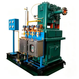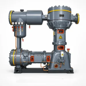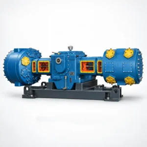
Description
The 4M-series nitrogen compressor — built under the 4MW model designation — is the largest reciprocating frame in this product family. A four-column, four-stage configuration handles flows of 80–135 m³/min at discharge pressures of 0.80 MPa (4MW-135/1.7–8) and 3.0 MPa (4MW-80/30 and 4MW-100/30), with motor power requirements of 900–1,200 kW on 6 kV or 10 kV medium-voltage supply. These are not general-purpose machines — they are purpose-built for the largest air separation units, major petrochemical nitrogen consumers, and high-capacity pipeline injection applications where no smaller frame can meet the flow requirement with a single compressor train.
The 4MW designation encodes the architecture: four columns (四列), four stages (四级), medium-heavy frame class. Machine weights run from 26.0 t to 26.5 t, requiring engineered concrete foundations with dynamic load analysis before installation. All four cylinder banks use oil-free PTFE-composite piston rings and rod packing — the crankcase and crosshead guide lubrication never contacts the nitrogen gas path.
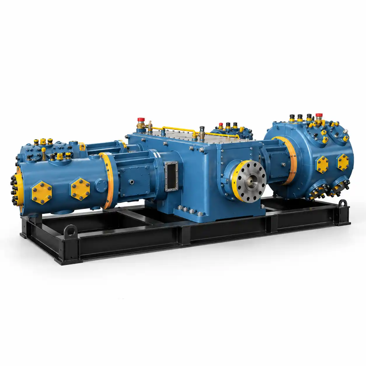
Four-Column Nitrogen Compressor Architecture: Why the 4MW Frame Is Designed the Way It Is at 80–135 m³/min
At 80–135 m³/min, a two-column frame (L-series or D-series) would require cylinder bores too large to maintain practical piston speeds and acceptable gas velocity through the valves. The four-column arrangement solves this by distributing each stage across two parallel cylinder banks — effectively doubling the cylinder count without increasing bore size beyond what can be reliably manufactured and maintained with oil-free piston rings.
The mechanical consequences are significant:
- Dynamic balance: Four-column opposed layout cancels primary and secondary inertia forces more completely than two-column frames. At this power level — 900–1,200 kW — residual unbalanced forces determine whether the foundation can be an isolated pad or requires a full inertia block. The 4MW frame uses a four-throw crankshaft with a 90° crank arrangement, which produces a much smoother torque profile than a two-column machine of equivalent power.
- Four stages: At 3.0 MPa outlet from atmospheric inlet, the overall compression ratio is 29.7:1. Four stages of approximately 2.3:1 each keep per-stage discharge temperature below 120°C — lower than the three-stage 3ZW (which runs ~140°C per stage) and significantly below the safe operating limit of PTFE packing. Lower stage temperatures translate directly to longer packing and valve life at this duty level.
- Inter-stage cooling: Three water-cooled inter-stage coolers plus an after-cooler, each with a moisture separator and automatic condensate drain. Cooling water flow requirement is 25–40 m³/h depending on the frame — confirm with our process engineering team before detailed design of the cooling system.
- Medium-voltage drive: Both 4MW frames require 6 kV or 10 kV supply. Motor starting method is typically reactor-start or soft-starter on MV; direct-on-line starting at 900–1,200 kW is not acceptable on most utility supply contracts. Confirm starting current limits with your power utility before ordering.
- Special variant (4MW-135/1.7–8): This frame operates at a variable discharge pressure range of 0.17–0.80 MPa with a fixed inlet condition of 0.17 MPa, rather than atmospheric inlet. It is specifically designed for integration downstream of a large-scale PSA unit or as the second-stage booster in a cascaded compression system. The inlet pressure specification must be confirmed at order — it cannot be changed in the field.
4M-Series Nitrogen Compressor Technical Specifications — Heavy-Duty Oil-Free N₂ Compressor 900–1200 kW 6kV / 10kV
All 4MW frames share the same base footprint (6800×4000×3200 mm) and four-column, four-stage (四列四级) configuration. Capacity is stated at design inlet conditions — note that the 4MW-135/1.7–8 has a non-atmospheric inlet.
| Model | Pattern | Capacity (m³/min) | Inlet Pressure (MPa) | Discharge Pressure (MPa) | Dimensions L×W×H (mm) | Weight (t) | Power (kW) | Voltage |
|---|---|---|---|---|---|---|---|---|
| 4MW-135/1.7–8 | Four-col, Four-stage | 135 | 0.17 MPa | 0.80 | 6800×4000×3200 | 26.00 | 1,200 | 6k or 10k |
| 4MW-80/30 | Four-col, Four-stage | 80 | 0.101 MPa (atm) | 3.00 | 6800×4000×3200 | 26.00 | 900 | 6k or 10k |
| 4MW-100/30 | Four-col, Four-stage | 100 | 0.101 MPa (atm) | 3.00 | 6800×4000×3200 | 26.50 | 1,200 | 6k or 10k |
Stage-by-Stage Pressure Profile (4MW-80/30 and 4MW-100/30, atmospheric inlet reference)
| Stage | Inlet Pressure (MPa) | Outlet Pressure (MPa) | Compression Ratio | Max Discharge Temp (°C) |
|---|---|---|---|---|
| Stage 1 | 0.101 | ~0.23 | ~2.3 | ≤ 110 |
| Stage 2 | ~0.22 (after cooler) | ~0.52 | ~2.3 | ≤ 115 |
| Stage 3 | ~0.50 (after cooler) | ~1.20 | ~2.4 | ≤ 120 |
| Stage 4 | ~1.15 (after cooler) | 3.00 | ~2.6 | ≤ 120 |
Values are nominal design points at rated capacity and 30°C cooling water inlet. Actual inter-stage pressures will vary with cooling water temperature, gas inlet conditions, and valve condition. The 4MW-135/1.7–8 has a different stage pressure profile due to its elevated inlet pressure — contact us for that machine’s certified data sheet.
Where Heavy-Duty 4MW Nitrogen Compressors Are Installed: Large-Scale Industrial N₂ Applications
Large Air Separation Unit (ASU) N₂ Compression
Cryogenic ASUs producing 500–1,500 Nm³/h of product nitrogen require compression trains capable of handling 80–135 m³/min at the process stage pressures dictated by the downstream distribution network. The 4MW-100/30 is the standard specification for ASUs in this range when distribution pressure is 3.0 MPa; the 4MW-135/1.7–8 covers the case where the cold box delivers nitrogen at 0.17 MPa and the plant needs to boost to 0.80 MPa pipeline pressure in a single machine.
Petrochemical Plant N₂ Infrastructure
Large ethylene crackers, methanol synthesis plants, and ammonia production facilities maintain nitrogen rings at 2.5–3.0 MPa for purging, blanketing, and emergency pressurization of process vessels. A single 4MW-80/30 or 4MW-100/30 train can supply the entire plant nitrogen header without paralleling smaller units, which reduces instrumentation and control complexity significantly.
Steel Plant Blast Furnace and Converter N₂
Basic oxygen furnace (BOF) converters require nitrogen for lance purging, stirring, and slag splashing at 2.0–3.0 MPa and high flow rates. Integrated steel mills with multiple converter vessels consume 60–120 m³/min of N₂ continuously during production campaigns. The 4MW frame handles this demand in a single train, avoiding the maintenance overhead of running three or four smaller machines in parallel.
Coal Chemical and Gasification Plants
Coal gasification, coal-to-liquids (CTL), and coal-to-chemicals (CTC) plants use nitrogen extensively for coal lock hopper pressurization, syngas purge trains, and catalyst regeneration purging at 2.5–3.0 MPa. These plants are also among the most demanding environments for compressor reliability — planned downtime windows are narrow and unplanned outages are extremely costly. The 4MW frame is sized and constructed to run continuously for 8,000 hours between major inspections.
Engineering Requirements for 4MW Heavy-Duty N₂ Compressor Projects: Foundation, Utilities, and MV Power
The 4MW frame is a project machine, not a catalog item you drop into an existing room. The following engineering inputs are required before we can issue a final quotation — submit them as part of your technical inquiry to avoid revision cycles:
Foundation
Machine weight 26–26.5 t; dynamic unbalanced forces to be provided by our mechanical engineering group after frame selection. Foundation must be isolated from the building structure with expansion joints. Subsoil bearing capacity data (SPT or CPT test results) required for foundation design. Minimum concrete grade C30; rebar layout and mat thickness to be specified by a licensed structural engineer using our dynamic load data.
Medium-Voltage Power Supply
Motor rated at 900 kW (4MW-80/30) or 1,200 kW (4MW-100/30 and 4MW-135/1.7–8) at 6 kV or 10 kV. Starting current at rated voltage: 5–6× FLA with reactor start; 3–4× FLA with VSD starting. Provide utility fault current data (symmetrical fault MVA at the MV bus) and confirm acceptable starting current limits before motor specification is finalised.
Cooling Water System
Total cooling water demand: 25–40 m³/h at ≤ 30°C inlet; 45°C max return temperature. Cooling circuit must be closed-loop or chemically treated once-through. Fouling factor design: 0.0002 m²·K/W. Provide water analysis (hardness, chloride, pH, TDS) — cooling water quality determines whether tube bundle material is carbon steel or stainless steel; this affects lead time.
N₂ Inlet Conditions
For 4MW-80/30 and 4MW-100/30: atmospheric inlet (0.101 MPa) is the design basis. For 4MW-135/1.7–8: inlet must be 0.17 MPa ± 5% — pressure regulation upstream of the compressor inlet is mandatory. All frames: inlet dew point ≤ −40°C at line pressure; inlet temperature ≤ 40°C; no entrained liquid. Provide N₂ purity certificate (O₂ content, moisture, hydrocarbon) from your source.
Complete Nitrogen Compressor Series Comparison: Choosing Between D, L, Z, 3Z, and 4M Frames
All five series use oil-free cylinder technology and share spare-parts families across overlapping frame sizes. The selection matrix below covers the full range:
| Series | Columns / Stages | Capacity (m³/min) | Pressure (MPa) | Power (kW) | Voltage | Weight (t) | Typical Use Case |
|---|---|---|---|---|---|---|---|
| Z-Series (ZW) | 2-col / 2–3 stage | 0.7–20 | 0.60–3.0 | 11–160 | 380 V | 0.38–6.0 | Labs, electronics, laser cutting, small plants |
| 3Z-Series (3ZW) | 3-col / 3-stage | 6–9.5 | 3.0 | 75–110 | 380 V | 3.0–3.5 | Cylinder filling, pipeline testing, rubber vulcanization |
| L-Series (LW) | 2-col / 1–3 stage | 7–102 | 0.20–3.0 | 45–350 | 380 V / 6–10 kV | 1.8–6.6 | Mid-size ASU, chemical, pharma, pipeline purge |
| D-Series (DW) | 2-col / 2–4 stage | 43–150 | 0.32–3.20 | 500–850 | 6–10 kV | 13–19 | Large ASU, petrochemical N₂ boosting |
| 4M-Series (4MW) | 4-col / 4-stage | 80–135 | 0.80–3.0 | 900–1,200 | 6–10 kV | 26.0–26.5 | Large ASU, steel, coal chemical, major petrochemical |
Lead Time, Factory Acceptance Testing, and Project Support for 4MW Large Nitrogen Compressor Orders
Standard production lead time for 4MW frames is 150–180 days from technically approved drawings, confirmed scope of supply, and advance payment receipt. The critical path is typically the MV motor — specify voltage (6 kV or 10 kV) and starting method at inquiry stage to allow early motor commitment.
Factory Acceptance Testing (FAT) is conducted as standard on all 4MW units and includes:
- Mechanical run test at no-load for 4 hours minimum, verifying bearing temperatures, vibration levels at all four columns, and oil system performance
- Pressure test of all gas-side components at 1.5× design pressure with nitrogen
- Verification of stage inter-pressures against the certified design data sheet under load conditions (nitrogen gas, at rated capacity)
- Functional test of all instrumentation: pressure switches, temperature sensors, vibration monitors, lube oil pressure switches, and emergency shutdown logic
- Witness testing by client inspector available; advise at order placement to allow schedule coordination
Commissioning supervision is available for 4MW installations. Our commissioning engineers have experience with startup procedures at large ASUs and petrochemical sites across China, the Middle East, and Southeast Asia. On-site work scope covers foundation grouting verification, piping connection review, first-fill lubrication, pre-start checklist, startup sequence supervision, and performance verification at rated conditions.
Start Your 4MW Nitrogen Compressor Inquiry
To receive a meaningful quotation, send us: required capacity (m³/min), inlet pressure (MPa), outlet pressure (MPa), N₂ source type, available voltage (6 kV or 10 kV), cooling water supply temperature, and any site constraints. Incomplete inquiries delay quotation — the more you tell us upfront, the faster we can respond.