Description
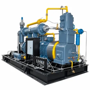
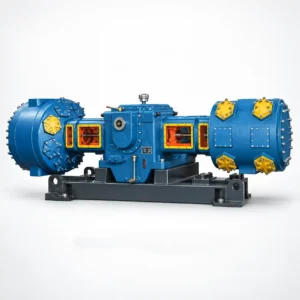
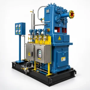
The L-series nitrogen compressor is a two-column, single- or two-stage reciprocating machine covering the widest capacity range in our N₂ compression lineup — from 7 m³/min (LW-7/30) up to 102 m³/min (LW-102/2) — at discharge pressures between 0.20 MPa and 3.0 MPa. The L-frame configuration places cylinders in an opposed, balanced arrangement that keeps base vibration low without the large footprint of a four-column machine, and virtually all models in the low-to-medium pressure range run on standard 380 V supply, making this the most straightforward frame to integrate into existing plant infrastructure.
Like all frames in this product family, L-series cylinders use oil-free piston rings and rod packing. Nitrogen purity at the compressor outlet is not degraded by compressor lubricant — the crankcase runs on force-feed oil, but that oil never contacts the gas path.
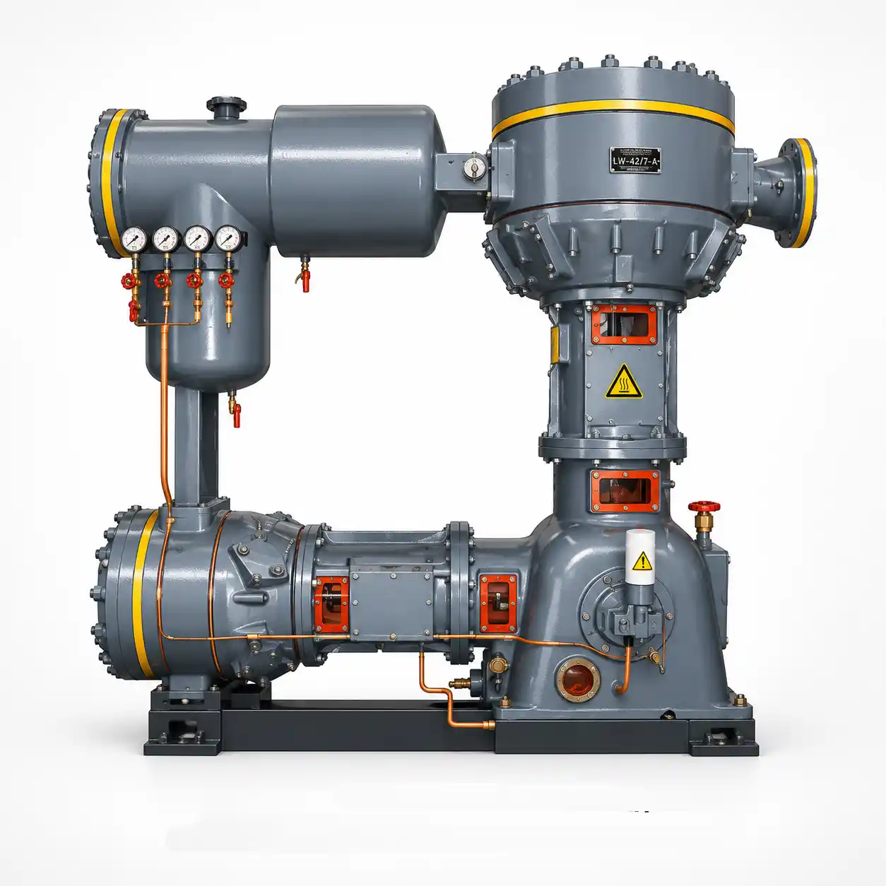
L-Series Nitrogen Compressor for Air Separation and Pipeline Distribution: What the Frame Delivers
The “L” designation in Chinese industrial compressor classification refers to 两列 (two-column) configuration where one or two compression stages are distributed across opposing cylinder banks. This opposed layout is mechanically significant: primary inertia forces from opposing pistons largely cancel, which means the L-frame transmits less dynamic load into its foundation than a single-column machine of the same swept volume.
Within the L-series for nitrogen service, two sub-groups exist:
- Single-stage frames (二列一级): LW-70/2, LW-102/2, LW-35/2.5, LW-33/3, LW-13.1/2 — used where inlet N₂ is near atmospheric and outlet pressure is below 0.30 MPa. These are the primary boosters installed directly at the discharge of cryogenic cold boxes.
- Two-stage frames (二列二级): LW-13/5, LW-20/6, LW-42/6, LW-10/8, LW-10/15, LW-24/16, LW-7/30, LW-9.5/30, LW-10/30, LW-17/30, LW-20/30, LW-33/30 — used for medium-to-high pressure service up to 3.0 MPa. A two-stage arrangement reduces the compression ratio per stage, lowers discharge temperature, and significantly extends valve and piston ring life compared to a single-stage machine working the same pressure differential.
- Cooling: Water-cooled inter-stage coolers and after-cooler on all two-stage frames; after-cooler only on single-stage frames. Closed-loop cooling water preferred; once-through acceptable where water quality is controlled.
- Drive voltage: 380 V for all frames up to 250 kW (LW-70/2, LW-24/16, LW-33/30, etc.); 380 V / 6 kV / 10 kV selectable for LW-42/6 (240–250 kW) and LW-33/30 (350 kW); 6 kV or 10 kV required for LW-70/2 (250 kW) and LW-102/2 (350 kW) due to motor size. Check the specifications table for each model.
- Base frame: Welded steel skid; cast iron cylinders with replaceable dry-running liners; chrome-plated piston rods standard on N₂ service to control rod seal wear.
L-Series Nitrogen Compressor Full Specification Table — Medium-Pressure Oil-Free N₂ Compressor 380 V to 10 kV
Model numbers follow the convention LW-[Capacity]/[Pressure × 10] — LW-20/6 delivers 20 m³/min at 0.60 MPa. Capacity is measured at atmospheric inlet conditions (0.101 MPa, 20°C) unless noted.
| Model | Pattern | Capacity (m³/min) | Discharge Pressure (MPa) | Dimensions L×W×H (mm) | Weight (t) | Power (kW) | Voltage (V) |
|---|---|---|---|---|---|---|---|
| SINGLE-STAGE FRAMES (二列一级) — Low-Pressure N₂ Boosting ≤ 0.30 MPa | |||||||
| LW-70/2 | Two-col, One-stage | 70 | 0.20 | 3260×1655×2548 | 5.00 | 250 | 6k or 10k |
| LW-102/2 | Two-col, One-stage | 102 | 0.20 | 3156×2465×2575 | 6.20 | 350 | 6k or 10k |
| LW-35/2.5 | Two-col, One-stage | 35 | 0.25 | 3136×1550×2900 | 3.40 | 132 | 380 |
| LW-33/3 | Two-col, One-stage | 33 | 0.30 | 3140×1550×2445 | 3.40 | 132 | 380 |
| LW-13.1/2 | Two-col, One-stage | 13.1 | 0.20 | 2420×910×2170 | 1.80 | 45 | 380 |
| TWO-STAGE FRAMES (二列二级) — Medium to High Pressure N₂ Service 0.50–3.0 MPa | |||||||
| LW-13/5 | Two-col, Two-stage | 13 | 0.50 | 2340×910×2070 | 1.80 | 65 | 380 |
| LW-20/6 | Two-col, Two-stage | 20 | 0.60 | 2630×1550×2332 | 3.00 | 132 | 380 |
| LW-42/6 | Two-col, Two-stage | 42 | 0.60 | 3260×1655×2548 | 4.50 | 240 (250) | 380 / 6k or 10k |
| LW-10/8 | Two-col, Two-stage | 10 | 0.80 | 2340×910×2070 | 1.80 | 65 | 380 |
| LW-10/15 | Two-col, Two-stage | 10 | 1.50 | 2790×1550×2590 | 3.00 | 110 | 380 |
| LW-24/16 | Two-col, Two-stage | 24 | 1.60 | 3920×1800×2465 | 6.60 | 250 | 380 / 6k or 10k |
| THREE-STAGE FRAMES (二列三级) — High-Pressure N₂ Service 3.0 MPa | |||||||
| LW-7/30 | Two-col, Three-stage | 7 | 3.00 | 3687×1100×2273 | 2.70 | 75 | 380 |
| LW-9.5/30 | Two-col, Three-stage | 9.5 | 3.00 | 3127×1550×2543 | 3.70 | 110 | 380 |
| LW-10/30 | Two-col, Three-stage | 10 | 3.00 | 3127×1550×2543 | 3.70 | 132 | 380 |
| LW-17/30 | Two-col, Three-stage | 17 | 3.00 | 2950×1800×2440 | 5.00 | 220 | 380 / 6k or 10k |
| LW-20/30 | Two-col, Three-stage | 20 | 3.00 | 3500×2600×1850 | 6.00 | 240 | 380 / 6k or 10k |
| LW-33/30 | Two-col, Three-stage | 33 | 3.00 | 3065×1685×2440 | 6.60 | 350 | 6k or 10k |
* LW-42/6 motor is rated 240 kW standard / 250 kW optional. Both voltage variants available. Dimensions are nominal; certified GA drawings issued at order confirmation. All capacity figures at atmospheric inlet (0.101 MPa, 20°C).
Where the L-Series Two-Column N₂ Compressor Gets Specified: Application Profiles by Pressure Range
0.20–0.30 MPa — ASU Product N₂ Boosting
LW-33/3, LW-35/2.5, LW-70/2, and LW-102/2 are installed immediately downstream of cryogenic air separation cold boxes to raise low-pressure product nitrogen to plant distribution pressure. The single-stage design keeps inter-stage complexity to a minimum; the 380 V motor on the 35 and 33 m³/min frames avoids the need for a dedicated MV transformer room.
0.50–0.80 MPa — Furnace Atmosphere & Tank Blanketing
LW-13/5, LW-20/6, LW-42/6, and LW-10/8 cover the operating range for continuous-feed heat treatment furnaces, float glass lines, and large-volume storage tank blanketing systems. The LW-20/6 at 132 kW / 380 V is the most common selection for mid-size steel and metalworking facilities that generate N₂ on-site from a PSA unit.
1.50–1.60 MPa — Chemical Reactor N₂ Charging
LW-10/15 and LW-24/16 are specified where reactor vessels require N₂ purge cycles at 1.5–1.6 MPa before and after batch runs — typical in pharmaceutical API synthesis, specialty polymer production, and fine chemical manufacturing where hydrocarbon exclusion is critical during loading and unloading operations.
3.0 MPa — Pipeline Hydrostatic Testing (N₂ Substitute)
The three-stage LW-7/30 through LW-33/30 are used for N₂ pressure testing of piping systems where water hydrostatic testing is not permitted — elevated pipeline sections susceptible to freeze damage, stainless steel lines where chloride stress corrosion cracking is a concern, or any system where drying-out time after a hydro test is not acceptable.
L-Series vs. D-Series: Choosing the Right Oil-Free Nitrogen Compressor Frame for Your Flow and Pressure Requirements
The most common selection question we receive is whether to specify an L-series or a D-series frame. The decision tree is straightforward:
| Criterion | L-Series | D-Series |
|---|---|---|
| Motor voltage | 380 V available on most frames | 6 kV / 10 kV required on all frames |
| Capacity range | 7–102 m³/min | 43–150 m³/min |
| Pressure range | 0.20–3.0 MPa | 0.32–3.20 MPa |
| Machine weight | 1.8–6.6 t | 13–19 t |
| Best fit scenario | Existing 380 V plant; small-to-medium ASU; space-limited compressor room | Large ASU with MV infrastructure; very high flow demand (>100 m³/min) |
Additional sizing considerations specific to the L-series:
- Stage count: If your outlet pressure exceeds 0.35 MPa, specify a two-stage frame to keep the compression ratio per stage below 4:1. A single-stage machine working a 0.6 MPa outlet from atmospheric inlet compresses at a ratio of approximately 6:1 — valve wear accelerates significantly above 5:1.
- Inlet pressure from PSA vs. cryogenic ASU: PSA nitrogen typically exits at 0.12–0.18 MPa. This elevates the inlet pressure on the compressor, slightly reducing motor demand and effective compression ratio. Confirm with our engineers if inlet is above atmospheric — frame selection may shift to a slightly smaller model.
- Ambient temperature: Standard design is for a compressor room temperature of ≤40°C. For installations in tropical climates or poorly ventilated rooms, specify the high-ambient option; motor derating and cooling water temperature limits must be reviewed.
- Foundation: L-series frames are significantly lighter than D-series (1.8–6.6 t vs. 13–19 t), making them suitable for upper-floor installation in multi-story compressor buildings where slab load limits are a constraint. Dynamic load data available from the factory for any model.
Maintenance Intervals and Spare Parts Planning for the L-Series LW Nitrogen Compressor
The L-series shares its basic valve, piston ring, and packing geometry with several other frame families in this product line, which means spare parts interchangeability is high across your fleet if you operate multiple series.
| Component | Inspection Interval | Replacement Interval |
|---|---|---|
| Piston rings (PTFE-filled) | 4,000 h | 8,000 h or at wear limit |
| Rod packing sets | 4,000 h | 8,000 h or on leakage |
| Suction & discharge valves | 2,000 h (visual check) | 6,000–8,000 h |
| Crankcase oil change | 1,000 h (sample & analysis) | 2,000 h or on analysis result |
| Main & rod bearings | At major overhaul | 16,000–20,000 h |
| Cooler bundle inspection | Annual | On fouling or leak |
Intervals above are for continuous-duty operation on clean, dry nitrogen (dew point ≤ −40°C at line pressure). Wet or contaminated inlet gas shortens packing and valve life significantly — add inlet filtration and a moisture separator if your N₂ source quality is uncertain.
Get a Quote for Your L-Series LW Nitrogen Compressor
Tell us your required flow rate (m³/min), outlet pressure (MPa), inlet N₂ source (ASU / PSA), and site voltage. We’ll confirm the right LW frame and respond with a formal quotation within 2 business days.