Description
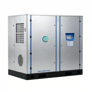
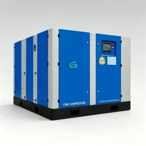
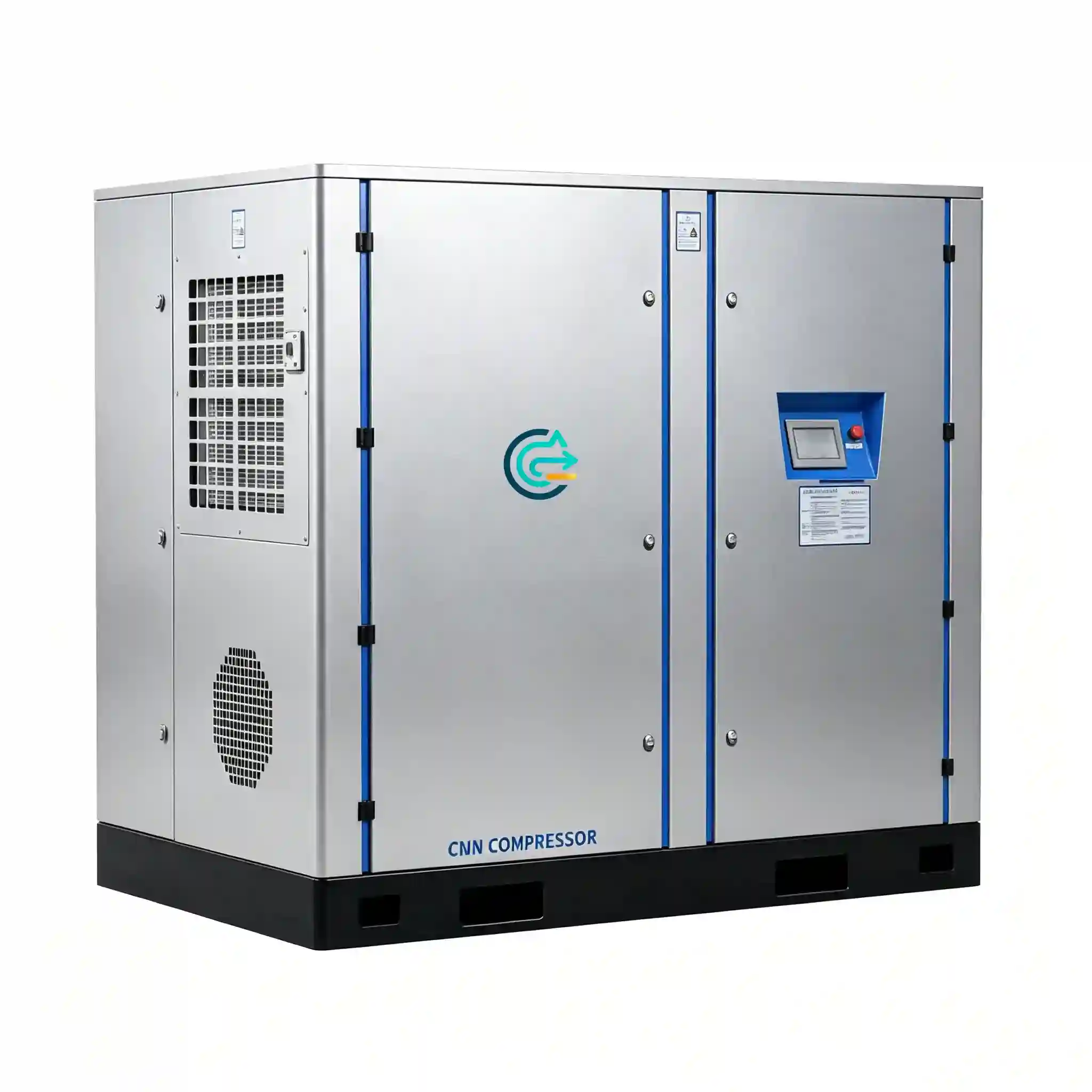
Heavy Duty Medium Pressure Screw Compressor — CN Series
90–160 kW oil-injected rotary screw compression at 20–40 bar working pressure — engineered for large factories, continuous production plants, and heavy compressed air users requiring sustained high-flow output with minimal downtime. Four models covering 16.9 to 31.5 m³/min FAD, all VFD-equipped for demand-matched operation.
- Working Pressure: 20 – 40 bar (290 – 580 psi)
- Motor Power Range: 90 – 160 kW
- FAD Capacity Range: 16.9 – 31.5 m³/min
- Models: CN180GV · CN200GV · CN240GV · CN320GV
- Drive: Variable frequency drive (VFD) — all models
- Target industries: steel plants · mining operations · chemical processing · heavy manufacturing
Overview — Large Factory Compressed Air at Medium Pressure
Why heavy-duty medium pressure compressors are specified
Steel mills, mining operations, chemical plants, and large-scale manufacturing facilities share a common compressed air requirement that standard utility compressors cannot satisfy: sustained high-flow output at pressures above the standard 7–10 bar utility range, maintained continuously across multi-shift and round-the-clock production schedules. A single production interruption caused by compressor underperformance or unplanned shutdown in these environments has measurable financial consequences — stoppage costs in continuous process industries are measured in thousands of dollars per hour.
The CN Series addresses this requirement directly. At 90–160 kW motor power and 16.9–31.5 m³/min FAD, these machines are sized for plant-scale compressed air demand — not supplementary capacity. The all-VFD configuration across the CN Series range reflects the operating reality in large industrial plants: demand is rarely constant, varying between shifts, product runs, and seasonal changes, and a compressor that cannot modulate output continuously wastes energy through excessive load/unload cycling.
Oil-injected design at medium pressure
The CN Series uses oil-injected two-stage rotary screw compression. Lubricating oil injected into the compression chamber seals rotor clearances, removes heat of compression between and within compression stages, and lubricates the air end bearings and timing gears. After compression, a high-efficiency oil separator removes the bulk of the oil — residual carry-over in delivered compressed air is 1–5 ppm by mass after the separator, reducible to 0.01 ppm with downstream coalescing filtration.
For steel plants, mining, chemical processing, and heavy manufacturing — where compressed air serves pneumatic actuators, conveying systems, cooling circuits, and process utilities rather than food or pharmaceutical product contact — the oil-injected specification is technically appropriate, operationally reliable, and substantially more cost-effective than oil-free machines at equivalent power and pressure. The efficiency advantage of oil-injected compression at 20–40 bar (typically 8–12% lower specific power than oil-free at equivalent pressure) is significant at the 90–160 kW power level running on a continuous-duty schedule.
VFD operation across the entire range
All CN Series models are equipped with variable frequency drive (VFD) motor control as standard. This is not an optional upgrade — it is the correct configuration for large industrial compressed air systems, where demand variation is the norm rather than the exception. VFD control modulates motor speed continuously to match compressor output to instantaneous air demand, maintaining discharge pressure within ±0.2 bar of set point without load/unload cycling. At large-plant scale, the energy savings from VFD operation at partial load are substantial: at 50% demand, a VFD unit saves approximately 28–32% motor energy compared to a fixed-speed machine of equivalent rated FAD operating in load/unload mode. At 160 kW continuous duty, this represents approximately 45–50 kW reduction in power draw at half load — thousands of dollars annually at industrial electricity rates.
CN Series — Technical Specifications
FAD values are measured at the compressor discharge flange per ISO 1217 Annex C at rated speed. Reference conditions: 20°C inlet temperature, 1 bar(a) inlet pressure, 0% relative humidity. All models are VFD-equipped; FAD varies across the VFD operating speed range — figures below are at rated maximum speed.
| Model | Motor Power (kW) | Pressure Range (bar) | FAD (m³/min) | FAD (cfm approx.) | Drive | Typical Application |
|---|---|---|---|---|---|---|
| CN180GV | 90 | 20 – 40 | 16.9 | ~597 | VFD | Large factory base-load, continuous manufacturing air supply |
| CN200GV | 90 | 20 – 40 | 17.8 | ~629 | VFD | High-flow factory networks, multi-line production facilities |
| CN240GV | 132 | 20 – 40 | 24.0 | ~848 | VFD | Steel plant instrument air, chemical process utilities, mining |
| CN320GV | 160 | 20 – 40 | 31.5 | ~1,112 | VFD | Highest flow in range; large continuous-process plants, N+1 redundancy systems |
| Parameter | Specification |
|---|---|
| Compression type | Two-stage oil-injected rotary screw |
| Drive | Variable frequency drive (VFD) — all models standard |
| VFD pressure control accuracy | ±0.2 bar of set point across operating speed range |
| Oil content at separator discharge | 1 – 5 ppm by mass; reducible to 0.01 ppm with downstream 0.01 μm coalescing filter |
| Working pressure range | 20 – 40 bar (290 – 580 psi) — specify required pressure at time of order |
| Cooling method | Air-cooled (standard); water-cooled configuration available on request |
| Lubrication oil type | Synthetic compressor oil, ISO VG 46 or VG 68 (manufacturer specification) |
| Oil separator element service interval | 3,000 – 4,000 hours; replace at differential pressure indicator threshold |
| Compressor oil change interval | 2,000 hours (synthetic oil) |
| Control system | PLC-based; continuous modulation via VFD; remote monitoring outputs standard |
| Communication outputs | Modbus RTU / RS-485 standard; optional Profibus DP or Ethernet/IP for SCADA |
| Inlet filtration | Dry-type panel filter, ≤ 5 μm particulate; differential pressure monitoring |
| Noise level | ≤ 78 dB(A) at 1 m (full load, free-field conditions) |
| Power supply | 380/400/415 V, 3-phase, 50/60 Hz; medium voltage (6 kV / 10 kV) on request for CN240GV and CN320GV |
| Ambient operating range | +5°C to +40°C (air-cooled standard); +5°C to +45°C (water-cooled configuration) |
| Altitude limit (standard) | 1,000 m ASL; derated output above — consult engineering with site altitude |
| Protection rating | IP54 standard; IP55 available on request |
| Air end bearing design life | 40,000+ hours L10 calculated life at rated load and speed |
Engineering Advantages for Heavy Industrial Operation
Airflow demand calculation for large plants
Correct compressor sizing in a large industrial plant begins with a measured or calculated demand profile, not a nameplate summation. The nameplate flow consumption figures on individual pneumatic tools, actuators, and process equipment overstate actual demand because no plant runs all equipment at full load simultaneously. The correct approach for a steel plant, mine, or chemical facility is to apply a demand diversity factor — typically 0.55–0.70 for a mixed industrial plant with varied equipment types — to the sum of all individual consumer nameplate figures. Instrument air circuits are an exception: control valves and positioners must be assumed at simultaneous peak demand during process upsets, when multiple valves open at once.
For a plant with 400 individual pneumatic consumers averaging 0.1 m³/min each (total nameplate: 40 m³/min), applying a 0.70 diversity factor yields a design demand of 28 m³/min — within the CN320GV’s 31.5 m³/min rated capacity, with margin for system losses and future additions. For plants with measured demand data (from flow meters on existing compressors), use the measured peak demand plus 15% growth margin as the sizing basis rather than nameplate calculations.
Compressor sizing methodology
Once demand FAD is established, the compressor selection must account for the difference between nameplate FAD (measured at 20°C reference inlet, 1 bar, 0% humidity) and actual FAD at site conditions. FAD decreases from nameplate under the following conditions:
- Ambient temperature above 20°C: approximately 1% FAD reduction per 3°C above reference. At 40°C ambient (common in steel plants near furnace areas, and in desert-climate mining operations), FAD is approximately 6–7% below nameplate.
- Altitude above 1,000 m ASL: lower inlet air density reduces volumetric efficiency. At 2,000 m ASL, FAD is approximately 8–10% below sea-level nameplate; at 3,000 m ASL, reduction reaches 14–18%.
- Inlet filter fouling: a partially blocked inlet filter increases pressure drop at the air end inlet, reducing effective compression ratio and FAD. Inlet filter differential pressure should be monitored continuously and element replaced before it becomes a FAD restriction.
For a CN320GV (31.5 m³/min nameplate FAD) installed at 35°C ambient and 1,500 m altitude, actual available FAD is approximately 31.5 × 0.95 (temperature correction) × 0.94 (altitude correction) ≈ 28.1 m³/min. This corrected figure, not the nameplate, is what the plant compressed air system can rely on at continuous duty.
Long-term operation factors
Compressors in steel plants, mines, and chemical facilities accumulate operating hours faster than in most industrial environments — 7,000–8,500 hours per year is typical for a continuous-process facility running around the clock. Over a 10-year service life, a CN320GV in this duty profile accumulates 70,000–85,000 operating hours. The design choices that determine whether a machine reaches this service life without major unplanned downtime are:
- Air end bearing selection: the CN Series uses oversized bearings specified for L10 life exceeding 40,000 hours at rated load and speed — equivalent to approximately 5 years of continuous operation before the first scheduled bearing inspection.
- Oil system capacity: a larger oil charge and a higher oil-to-air ratio reduces oil temperature at the compression stage and extends oil change intervals. Oil operating temperature should be maintained above the oil dewpoint (to prevent water contamination) and below 90°C (to prevent accelerated degradation).
- VFD drive reliability: VFD drives in industrial environments are exposed to harmonic distortion, voltage spikes, and thermal cycling. The CN Series VFD enclosure is rated IP54, with forced-air cooling and thermal protection. VFD capacitors have a finite service life (typically 10–15 years at rated conditions) and should be included in the long-term maintenance plan.
- Cooling system maintenance: air-cooled models reject 85–90% of input power as heat through the oil cooler and aftercooler. Fin fouling from airborne dust, oil mist, or process vapors increases thermal resistance and raises operating temperatures across the machine. Cooler fin cleaning should be scheduled every 2,000 hours in clean environments and every 500–1,000 hours in dusty industrial environments.
Maintenance requirements and service planning
At 90–160 kW and 16.9–31.5 m³/min, an unplanned CN Series shutdown has a larger production impact than a small compressor failure. Maintenance planning for machines in this class should be integrated into the plant’s overall preventive maintenance schedule, with parts pre-positioned for scheduled service tasks. The CN Series maintenance schedule:
- Every 500 hours: Inspect inlet air filter differential pressure. Replace filter element in dusty environments (steel plants, mining, foundries) — do not wait for the scheduled 2,000-hour interval if differential pressure is elevated.
- Every 1,000 hours: Check compressor oil level; verify oil cooler outlet temperature is within specification. Inspect all external connections for oil or air leaks.
- Every 2,000 hours: Compressor oil change (synthetic oil, ISO VG 46 or VG 68 as specified). Clean oil cooler and aftercooler fin surfaces. Inspect drive coupling or belt for wear. Verify all temperature and pressure sensors against calibrated reference instruments.
- Every 3,000–4,000 hours: Replace oil separator element when differential pressure indicator triggers the replacement threshold. Do not defer — elevated separator differential pressure reduces FAD and increases oil carry-over to downstream equipment.
- Every 4,000 hours: Inspect inlet valve, unloader valve, and minimum pressure valve for wear and correct operation. Check VFD cooling fan and filter for fouling. Verify PLC input signals against calibrated sensors.
- Every 8,000 hours: Air end bearing inspection. Check all internal shaft seals for condition. Inspect VFD DC bus capacitors and power module condition. Thermographic inspection of electrical connections.
- Every 16,000 hours: Major air end service — bearing replacement, rotor clearance measurement, internal seal replacement. This is typically performed at an authorized service facility with the air end removed from the machine.
N+1 redundancy for continuous-process plants
For steel mills, chemical plants, and mining operations where a compressor trip forces a production shutdown or creates a safety condition, N+1 redundancy is the standard design basis. In a two-machine configuration at the CN Series scale, the standby machine is maintained in a hot-standby state (pressurized, at operating temperature, VFD at minimum speed) and starts automatically within 5–10 seconds of the duty machine tripping or when header pressure drops below the secondary set point. For plants with demand in the 25–30 m³/min range, two CN240GV machines (24.0 m³/min each) in a duty/standby arrangement provides full capacity coverage when one machine is online and adequate emergency capacity when the standby starts on a duty machine fault.
Industrial Application Areas
Steel plants
Compressed air in steel manufacturing is used across multiple critical systems: oxygen lance control valves on basic oxygen furnaces (BOF) and electric arc furnaces (EAF), pneumatic actuators on ladle handling equipment, alloy addition conveying systems, rolling mill guide cooling, scale breaking on hot strip mills, and instrument air for process control loops throughout the plant. The instrument air requirement in a steel plant is the most critical from a reliability standpoint — loss of instrument air pressure causes control valves to fail to their safe position, which typically means a furnace or process shutdown.
Steel plant compressor rooms are among the most demanding operating environments for any mechanical equipment: ambient temperatures near furnace areas regularly exceed 35°C, airborne iron oxide and carbon dust foul inlet filters and cooler fins rapidly, and the electrical supply may be subject to voltage fluctuations from large motor starts on rolling mill drives. The CN Series is designed for this environment — IP54 enclosure, robust VFD with thermal protection, and maintenance intervals calibrated for high-ambient and high-particulate conditions. For plants near EAF or BOF operations, the water-cooled configuration eliminates the dependence on ambient air temperature for cooling performance.
At the flow rates required for a medium-to-large steel facility — instrument air demand alone often exceeds 20 m³/min — the CN240GV (24.0 m³/min) and CN320GV (31.5 m³/min) provide single-machine capacity that replaces multiple smaller compressors, reducing the maintenance footprint and simplifying the instrument air control architecture.
Mining operations
Surface and underground mining operations use compressed air for rock drill actuation, longhole drill string rotation, shotcrete spraying, pneumatic hoisting controls, ventilation door actuators, and dewatering pump controls. Mining compressed air systems have several characteristics that distinguish them from factory installations: the compressor may be located at the surface while the point of use is underground (requiring careful pressure loss calculations for long distribution runs), the operating altitude may be high (reducing FAD from nameplate), and the ambient environment is often extremely dusty.
At 20–40 bar working pressure, the CN Series covers the pressure requirement for underground rock drill operation (typically 17–25 bar at the drill head) and longhole drilling rigs (20–35 bar). The VFD drive on all CN Series models allows the compressor output to follow the highly variable demand profile of a mining operation — when multiple drills are operating simultaneously, the machine runs near full speed; when drills stop for bit changes or blasting, the machine modulates down without cycling on and off. For high-altitude mining sites (above 1,500 m ASL), request an altitude-corrected performance data sheet to confirm actual FAD at site conditions before specifying the model.
Chemical plants
Chemical processing facilities use compressed air for pneumatic control valves throughout the process plant, agitator drives on reaction vessels, purge air for analyzer instruments, ejector systems, and in some processes as a reactant or carrier gas. The defining compressed air requirement in a chemical plant is reliability — control valve air failure causes process upsets that can take hours to recover from, and in processes involving hazardous materials, loss of instrument air pressure is a safety event.
Chemical plant compressor installations must also address the ambient air quality: many chemical processes release corrosive vapors (chlorine, sulfur compounds, ammonia, acid mists) that can attack compressor components if drawn into the inlet. The CN Series inlet filter system provides particulate protection, but for installations near aggressive chemical vapor sources, the air inlet should be ducted to a clean air source outside the chemical process area, or an inlet air treatment system (activated carbon bed or scrubber) should be installed upstream of the compressor. Specify the chemical environment at time of inquiry so appropriate materials (stainless steel cooler tubes, epoxy-coated intercooler and aftercooler, corrosion-resistant fasteners) can be included in the configuration.
Heavy manufacturing
Large-scale heavy manufacturing — forge shops, large press shops, foundries, heavy fabrication facilities — uses compressed air at medium pressure for pneumatic press actuation, die-casting machine intensifiers, shot blast controls, and crane and handling equipment pneumatics. These applications share a characteristic demand profile: high peak demand during press or machine cycles, with lower demand between cycles. The VFD drive on all CN Series models is well-suited to this demand pattern — it modulates output during inter-cycle pauses rather than cycling on and off — but a properly sized receiver tank (minimum 30–50 liters per kW of installed compressor power) should be included in the system design to buffer peak demand spikes and reduce the rate-of-change requirement on the VFD speed control.
For forge shops and foundries specifically, the dusty and high-temperature ambient environment requires shorter inlet filter service intervals (200–300 hours rather than the standard 500 hours) and more frequent cooler fin cleaning. In facilities with open-hearth furnaces or induction heaters, radiant heat can raise the compressor room ambient above the 40°C operating limit for air-cooled machines — in these installations, specify the water-cooled configuration or ensure the compressor is located in a ventilated enclosure separate from the furnace area.
Compressor Selection Guide
Step 1 — Measure or calculate peak plant FAD demand
For a new plant, calculate total FAD demand by summing the individual consumption figures of all pneumatic consumers and applying a diversity factor of 0.55–0.70 depending on the plant type. For an existing plant with installed compressors, install flow meters on the compressor discharge lines and log demand over a full production week — capturing day shift, night shift, weekend, and production changeover states. The logged peak demand, not the average, is the design basis. Add 15% to the measured or calculated peak to account for system leakage (typically 10–20% of total flow in an unmanaged compressed air system) and future expansion.
Step 2 — Correct for site conditions
Apply the following corrections to the nameplate FAD before model selection:
- Ambient temperature correction: multiply nameplate FAD by [293 / (273 + T_ambient)] where T_ambient is the maximum expected ambient temperature in °C.
- Altitude correction: multiply by [1 – (altitude_m / 10,000)] as a first approximation; request precise altitude correction data from the engineering team for sites above 1,500 m ASL.
- Inlet filter correction: assume 2–3% FAD reduction to account for filter pressure drop at design flow with a partially loaded element (between service intervals).
Select the CN Series model whose corrected FAD at site conditions meets or exceeds the required plant demand plus the 15% margin established in Step 1.
Step 3 — Establish required working pressure
The CN Series is configurable across the 20–40 bar range. Specify the required discharge pressure based on the highest-pressure point of use in the system, with the following additions for system losses:
- Oil separator and aftercooler pressure drop: 0.5–1.0 bar
- Downstream filtration (coalescing filter assembly): 0.3–0.5 bar
- Distribution piping losses (properly sized header at design flow): 0.2–0.5 bar
- VFD pressure control band: ±0.2 bar — the machine maintains set pressure within this band, so no additional margin is needed for control band
Higher discharge pressure means higher specific power — each additional bar above the minimum required increases energy consumption by approximately 3–4% at constant flow. Specify the minimum pressure that satisfies all points of use, not the maximum the machine can produce.
Step 4 — Determine redundancy configuration
For continuous-process plants where a compressor shutdown forces a production stoppage, specify a minimum of two machines in duty/standby configuration. For plants where partial production can continue at reduced compressed air flow, a lead/lag configuration where the lag machine starts at a secondary pressure set point provides partial redundancy without the cost of full N+1 capacity. The CN Series VFD control system supports both configurations through the PLC sequencing logic.
| Required FAD at site conditions | Model | Motor Power (kW) | Nameplate FAD (m³/min) | Notes |
|---|---|---|---|---|
| Up to 16.9 m³/min (597 cfm) | CN180GV | 90 | 16.9 | Apply site correction before confirming; check ambient and altitude |
| 16.9 – 17.8 m³/min (597–629 cfm) | CN200GV | 90 | 17.8 | Higher FAD than CN180GV at same motor power — confirm pressure rating |
| 17.8 – 24.0 m³/min (629–848 cfm) | CN240GV | 132 | 24.0 | Standard choice for steel plant instrument air and chemical plant utilities |
| 24.0 – 31.5 m³/min (848–1,112 cfm) | CN320GV | 160 | 31.5 | Highest flow in range; confirm medium voltage availability for 160 kW if required |
Frequently Asked Questions
How do I calculate the correct compressor size for a large plant with many pneumatic consumers?
Start with the nameplate flow consumption figures of all pneumatic consumers in the plant. Sum these figures, then apply a diversity factor — typically 0.55–0.65 for a steel plant or mining operation (where equipment is rarely all running simultaneously), or 0.65–0.75 for a continuous production line (where demand is more consistent). This gives a design demand figure in m³/min or cfm. Add 15% to cover system leakage and future expansion. Then correct the resulting figure for site ambient temperature and altitude to determine the required nameplate FAD of the compressor. For an existing plant, replace the nameplate summation with flow meter measurements over a full production week — this is always more accurate than nameplate calculations.
What is the energy cost difference between a VFD compressor and a fixed-speed machine at this power level?
At 160 kW, the energy cost difference between VFD and fixed-speed operation at partial load is substantial. A fixed-speed machine in load/unload mode at 50% demand draws approximately 70–75% of full-load power (due to unloaded running losses). A VFD machine at 50% demand draws approximately 40–45% of full-load power. The difference — approximately 28–32 percentage points of rated power — represents approximately 45–50 kW at the 160 kW power level. At a typical industrial electricity rate of USD 0.08–0.12 per kWh and 7,000 operating hours per year, this difference amounts to USD 25,000–42,000 per year in energy cost savings for a single CN320GV operating at 50% average demand versus a fixed-speed equivalent. For a plant with two machines in duty/standby, the savings are per duty machine.
Can the CN Series operate in high-dust environments such as mining and steel plants?
Yes, with modified maintenance intervals and potentially supplementary inlet air treatment. The standard inlet filter removes particulate down to 5 μm, which is adequate for clean industrial environments. In high-dust environments — open-pit mining, steel plant floor areas near charging equipment, foundries, or quarries — the inlet filter should be inspected every 200–300 hours rather than the standard 500-hour interval, and replaced more frequently. For extremely dusty environments, a pre-filter or cyclone separator upstream of the standard inlet filter extends element life and reduces maintenance frequency. For mining applications where the compressor is located in an enclosed surface building with controlled air quality, standard maintenance intervals apply. Request site-specific inlet filtration recommendations when submitting the technical inquiry.
What downstream filtration is required for the compressed air from the CN Series?
The CN Series delivers oil-injected compressed air with 1–5 ppm residual oil after the on-board separator. For general factory utility air (pneumatic actuators, conveying, tooling), a single 1 μm coalescing filter downstream of the receiver is the standard configuration. For instrument air serving control valves and positioners in chemical or process plants, a two-stage filter assembly — 1 μm pre-filter followed by 0.01 μm high-efficiency coalescing filter — reduces residual oil to approximately 0.01 ppm, meeting ISO 8573-1 Class 1 for oil aerosol. All downstream filtration components must be rated for the working pressure of the system (20–40 bar) — standard 7–10 bar filter housings must not be used. For applications requiring oil vapor removal in addition to aerosol removal, add an activated-carbon adsorption filter after the coalescing stage.
What are the pressure vessel requirements for a 20–40 bar receiver tank?
A receiver tank operating at 20–40 bar is a high-pressure vessel requiring certification to the applicable national standard. In the United States: ASME Section VIII Division 1, stamped with MAWP at or above the system maximum working pressure. In the European Union: Pressure Equipment Directive 2014/68/EU, CE marked with Notified Body inspection certificate — at pressures above 10 bar and volumes above threshold values, Category III or IV classification applies, requiring a more rigorous conformity assessment than lower-pressure receivers. In Australia: AS/NZS 1200 and AS 4041. In the Middle East: country-specific regulations (SASO in Saudi Arabia, ESMA in UAE). The receiver must be equipped with a pressure relief valve set no higher than MAWP, automatic condensate drain, isolation valves, and a calibrated pressure gauge — all rated for the working pressure. Size the receiver at a minimum of 10 liters per kW of installed compressor power (1,600 liters for a CN320GV) to buffer demand peaks and reduce VFD speed change rate.
How does altitude affect the CN Series performance, and what corrections should be applied for high-altitude mining sites?
Altitude reduces inlet air density, which directly reduces FAD (volumetric flow referenced to inlet conditions) and also reduces motor cooling effectiveness for air-cooled motors. At 1,500 m ASL, FAD is approximately 85–87% of sea-level nameplate. At 2,500 m ASL, FAD is approximately 78–80% of nameplate. At 3,500 m ASL — relevant for high-altitude mining in the Andes, Tibetan Plateau, or East African highlands — FAD may be only 68–72% of nameplate. At these altitudes, motor derating is also required: a standard 160 kW motor rated to IEC 60034 must be derated to approximately 140–145 kW at 3,000 m ASL to prevent winding overheating due to reduced cooling air density. Submit your site altitude in the technical inquiry — the engineering team will provide altitude-corrected FAD and motor derating data for your specific elevation before model selection is confirmed.
What SCADA and remote monitoring capabilities are available for the CN Series?
All CN Series models include Modbus RTU over RS-485 as standard, supporting the following data registers: discharge pressure, discharge temperature, interstage pressure and temperature, oil temperature, motor current, motor speed (Hz), power consumption (kW), run hours, loaded hours, VFD fault code, PLC fault code, inlet filter differential pressure status, oil separator differential pressure status, and maintenance interval countdown for each scheduled service item. Optional fieldbus modules available: Profibus DP for Siemens S7 and compatible PLC systems; Ethernet/IP for Rockwell ControlLogix and Allen-Bradley systems; PROFINET for advanced Siemens TIA Portal environments. The PLC also provides hardwired I/O: potential-free run contact, fault contact, and remote start/stop input for DCS hardwired integration where fieldbus is not available. Specify the required communication protocol at time of order — fieldbus modules are factory-fitted and not field-installable on all models.
What is the lead time and spare parts availability for CN Series machines?
Standard CN Series models (CN180GV, CN200GV, CN240GV, CN320GV) in standard voltage and cooling configuration are available from stock or with a 4–8 week lead time depending on model and current inventory. Custom configurations — medium-voltage motors (6 kV or 10 kV), water-cooled heat exchangers, corrosion-resistant material options for chemical environments, or tropical climate packages — require 8–14 weeks from order confirmation. For critical-process installations where unplanned downtime is not acceptable, a recommended spare parts kit for the first 8,000 operating hours is available at time of machine order: this kit includes inlet filter elements, oil separator elements, a full oil charge, minor seal kits, and VFD cooling filters. Stocking this kit on-site eliminates the typical 2–5 day parts lead time for the most common service items and allows scheduled maintenance to be performed during planned production downtime windows.
Technical Inquiry — CN Series Heavy Duty Compressor Selection
Submit your plant operating requirements using the parameters listed below. A compressed air systems engineer will review your application and respond with a model recommendation, site-corrected FAD data, downstream system sizing, redundancy configuration recommendation, and dimensional drawing within 2 business days.
Required information for heavy-duty compressor selection
- Total required FAD at site conditions — m³/min, Nm³/h, or cfm; state whether this is measured data or a nameplate calculation
- Required working pressure at point of use — bar or psi; list the highest-pressure consumer and its pressure requirement
- Application description — industry type and specific end-uses of the compressed air (instrument air, conveying, tooling, process utilities)
- Air purity requirement — acceptable oil content class (ISO 8573-1) or confirm if downstream filtration is already in place
- Duty cycle — continuous 24/7 operation, multi-shift, or specify hours per day and days per week
- Demand profile — constant load, or variable; if variable, provide estimated minimum and maximum demand figures
- Site ambient temperature range — minimum and maximum °C or °F; note if compressor room is enclosed or open
- Installation altitude — meters or feet above sea level
- Power supply — voltage, phases, frequency, and available short-circuit current (kA); note if medium voltage (6 kV or 10 kV) is preferred
- Cooling preference — air-cooled or water-cooled; if water-cooled, confirm cooling water supply temperature and available flow rate
- Ambient air quality — note presence of dust, corrosive vapors, oil mist, or other contaminants at the proposed installation location
- Redundancy requirement — N+1 standby, duty/standby, or simplex; state consequences of compressor shutdown on production
- SCADA integration — fieldbus protocol required (Modbus, Profibus, Ethernet/IP, PROFINET) or hardwired I/O only
- Existing infrastructure — receiver tank size and pressure rating, distribution piping material and pressure class, existing filtration equipment
For greenfield installations, include a site drawing or preliminary plant layout showing the proposed compressor room location and distribution header routing. For retrofits or capacity upgrades, include the existing compressor nameplate data and current measured flow data if available.
Email: [email protected]
Response includes: model recommendation with site-corrected FAD, redundancy configuration, downstream filtration and receiver sizing, motor starting method confirmation, SCADA integration specification, and dimensional drawing for plant layout review. Custom configurations including medium-voltage motors, water-cooled heat exchangers, and high-altitude packages are confirmed at this stage.