Description
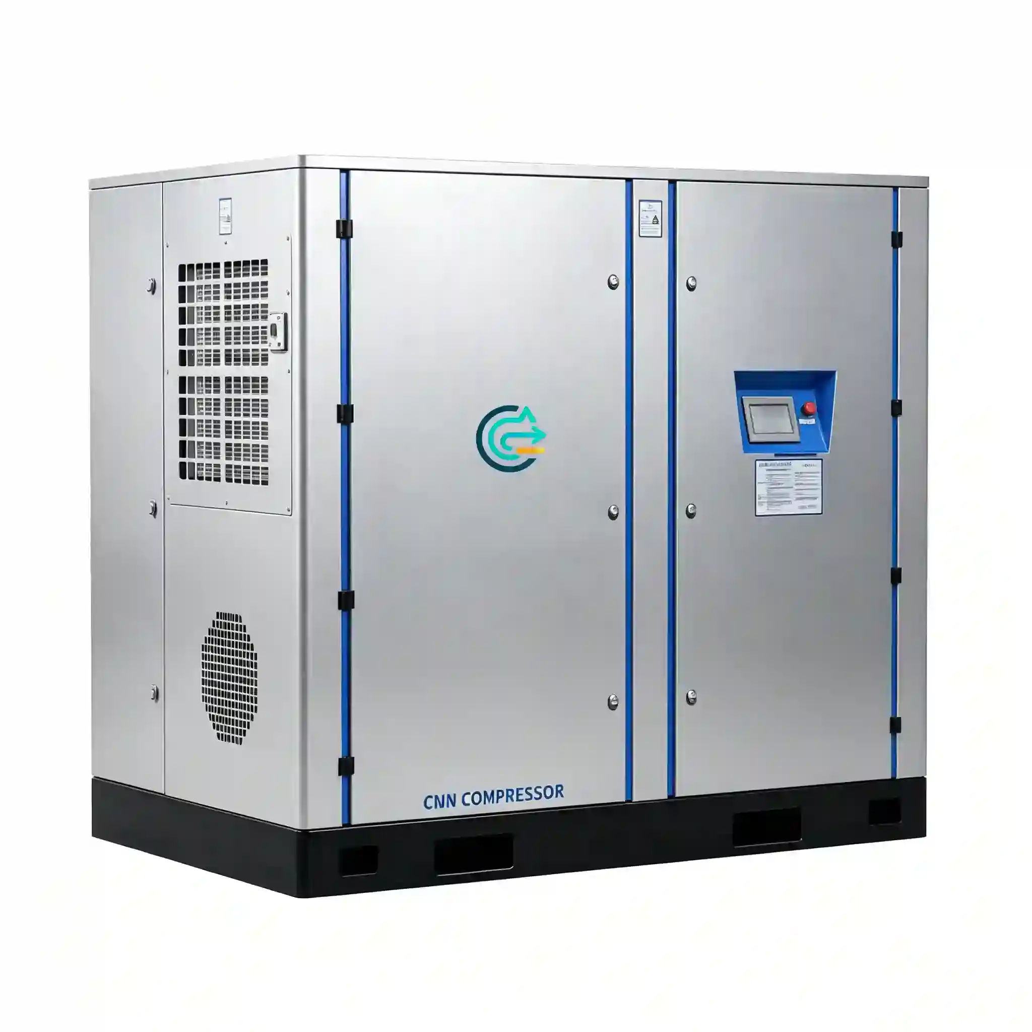
High Capacity Oil-Free Screw Compressor
100–250 kW two-stage oil-free rotary screw compression for large factory compressed air systems — continuous-duty operation with ISO 8573-1 Class 0 oil-free air output. Six models covering 8.4 to 24.6 m³/min FAD.
Industries served: steel manufacturing · chemical processing · electronics fabrication · precision manufacturing · food & beverage · pharmaceutical production
Large Factory Compressed Air Requirements
Why high-capacity compressors are specified
Industrial facilities above a certain production scale cannot be served efficiently by multiple small compressors alone. A steel processing plant, chemical reactor complex, or large electronics fabrication facility may require sustained compressed air flow in the range of 15–30 m³/min or higher — flow rates that a single standard 30–55 kW compressor cannot provide, and that a bank of small machines serves poorly in terms of energy efficiency, control complexity, and maintenance overhead.
A single high-capacity compressor in the 100–250 kW class addresses this directly. It reduces the number of machines on the plant floor, simplifies the control architecture, reduces the number of maintenance points, and allows a single large air end to operate closer to its design efficiency point rather than running multiple small machines at partial load.
Continuous duty versus cyclic service
High-capacity industrial compressors in process environments are not cyclic machines — they run at or near full load for extended periods, often 16–24 hours per day across multi-shift operations. The CM/G Series is designed specifically for this duty: the air end rotor bearings are rated for 40,000+ hour design life, the cooling system is sized for sustained operation at 40°C ambient, and the PLC control system is configured for unattended operation with remote monitoring outputs.
Oil-free requirement in high-capacity systems
At flow rates of 10–25 m³/min, the consequences of oil contamination in the compressed air system are proportionally larger. A high-capacity oil-flooded compressor passing even 1 ppm oil aerosol at 20 m³/min delivers approximately 20 mg of oil per minute into the distribution system — fouling instrument air lines, process sensors, pneumatic valve positioners, and product-contact surfaces continuously.
The CM/G Series eliminates this at the source. The two-stage oil-free air end produces ISO 8573-1 Class 0 compressed air — zero detected oil content — without relying on downstream coalescing filtration to achieve the classification. At high flow rates, this also eliminates the filter element cost and replacement labor associated with maintaining multiple high-flow coalescing filter assemblies.
CM/G Series — High Capacity Model Specifications
FAD values are measured at the compressor discharge flange per ISO 1217 Annex C. Reference conditions: 20°C inlet temperature, 1 bar(a) inlet pressure, 0% relative humidity. VFD models (CM100GV, CM220GV, CM250GV) show FAD range across the operating speed range.
| Model | Power (kW) | FAD (m³/min) | FAD (cfm) | Drive | Cooling | Notes |
|---|---|---|---|---|---|---|
| CM100GV | 100 | 8.4 – 9.6 | 297 – 339 | VFD | Air | Variable speed; demand-matched output across full FAD range |
| CM132G | 132 | 13.5 | 477 | Fixed | Air | Standard air-cooled; base-load continuous duty |
| CM132GW | 132 | 13.5 | 477 | Fixed | Water | Water-cooled; for restricted ventilation or high ambient installations |
| CM185G | 185 | 19.6 | 692 | Fixed | Air | High-output fixed speed; steel, chemical, large manufacturing |
| CM220GV | 220 | 24.6 | 869 | VFD | Air | Highest FAD in range; VFD for variable large-plant demand |
| CM250GV | 250 | 23.8 | 840 | VFD | Air | 250 kW rated; slightly lower FAD than CM220GV reflects higher pressure capability |
| Parameter | Specification |
|---|---|
| Compression type | Two-stage oil-free rotary screw |
| Oil content at discharge | ISO 8573-1 Class 0 (zero detected oil — aerosol, liquid, vapor) |
| Rotor material | PTFE-composite or PEEK-tipped coating; dry-running, no lubricant in compression chamber |
| Cooling — air-cooled models | Fin-and-tube aluminum intercooler and aftercooler; forced-draft fan cooling |
| Cooling — CM132GW water-cooled | Shell-and-tube intercooler and aftercooler; cooling water 15–25 L/min, ≤ 32°C inlet |
| Control system | PLC-based; load/unload (fixed speed) or continuous modulation (VFD models) |
| VFD pressure control accuracy | ±0.2 bar of set point (CM100GV, CM220GV, CM250GV) |
| Fixed-speed pressure control | ±0.3 bar of set point (CM132G, CM132GW, CM185G) |
| Inlet filtration | 3-stage, ≤ 3 μm particulate |
| Power supply | 380/400/415 V, 3-phase, 50/60 Hz; 6 kV and 10 kV medium voltage on request for CM185G–CM250GV |
| Ambient operating limit | +5°C to +40°C (air-cooled); +5°C to +45°C (CM132GW water-cooled) |
| Altitude limit (standard) | 1,000 m ASL; derated performance above — consult engineering |
| Communication outputs | Modbus RTU / RS-485; optional Profibus DP or Ethernet/IP for SCADA integration |
| Protection rating | IP54 enclosure (standard); IP55 available |
Performance comparison — fixed speed versus VFD at partial load
| Demand level (% of rated FAD) | Fixed-speed power draw | VFD power draw | Energy saving with VFD |
|---|---|---|---|
| 100% | 100% | 100% | — |
| 80% | ~88% | ~72% | ~16 percentage points |
| 60% | ~78% | ~52% | ~26 percentage points |
| 50% | ~72% | ~43% | ~29 percentage points |
| 40% | ~65% (load/unload cycling) | ~36% | ~29 percentage points |
At 250 kW rated power, a 29-percentage-point energy saving at 50% load represents approximately 72 kW reduction in continuous power draw — significant at industrial electricity rates.
Continuous Duty Design and Maintenance Considerations
Air end design for sustained high-load operation
Compressors in the 100–250 kW class in steel, chemical, and large manufacturing plants routinely accumulate 6,000–8,000 operating hours per year. The CM/G Series air end is engineered for this duty profile. Synchronizing gear materials and heat treatment are selected for the torque loads at these power levels. Rotor tip clearances are specified to account for differential thermal expansion at sustained operating temperature. Bearing selection targets a calculated L10 life exceeding 40,000 hours at rated load and speed.
Thermal management at high power
A 250 kW compressor rejects approximately 230–240 kW of heat through the intercooler, aftercooler, and machine casing. Air-cooled models require adequate machine room ventilation. As a rough guide: at 40°C ambient and a 5°C temperature rise allowance in the machine room, approximately 45,000–48,000 m³/h of room air change is required for the CM250GV.
The CM132GW water-cooled variant eliminates this constraint by routing all heat rejection through the cooling water circuit. For plants with an existing chilled water or cooling tower loop, the CM132GW simplifies the machine room thermal design substantially.
Scheduled maintenance intervals
- Every 500 hours: Inspect inlet air filter differential pressure indicator; replace cartridge if pressure drop exceeds 25 mbar. In dusty environments (steel plants, foundries), this interval may shorten to 200–300 hours.
- Every 2,000 hours: Verify electronic condensate drain operation. Check cooling fan belt tension on air-cooled models. Inspect inlet valve and unloader mechanism for wear.
- Every 4,000 hours: Gearbox oil change (ISO VG 100 or 150 synthetic gear oil). Inspect and clean intercooler and aftercooler fin surfaces. Verify all temperature and pressure sensors against calibrated reference.
- Every 8,000 hours: Air end rotor bearing inspection. Replace rotor tip seals. Full lubrication system inspection including gearbox seal condition.
- Every 16,000–24,000 hours: Rotor coating inspection and rebush or recoat as indicated by internal wear measurement. Air end overhaul task typically performed at an authorized service facility.
N+1 redundancy planning
For critical process air systems where a compressor trip would force a production line shutdown, a standby machine is standard practice. In a two-machine configuration, the standby unit starts automatically when the lead machine trips or when discharge pressure falls below the secondary set point. For large plants with demand in the 20–25 m³/min range, a CM185G (19.6 m³/min) as primary and a CM132G (13.5 m³/min) as standby provides adequate emergency capacity to maintain essential processes while the primary is taken offline for repair.
Remote monitoring and SCADA integration
The CM/G Series PLC provides Modbus RTU output as standard, with optional Profibus DP and Ethernet/IP modules for integration into plant SCADA or DCS systems. Available data points include: discharge pressure, discharge temperature, interstage pressure, interstage temperature, motor current, run hours, fault status, and maintenance interval countdown. This allows plant engineers to monitor compressor health remotely and schedule maintenance based on actual operating conditions.
Industrial Applications
Steel manufacturing
Compressed air in steel plants is used for oxygen lance controls, pneumatic valve actuators on BOF and EAF furnaces, conveying systems for alloy additions, cooling air for rolling mill guides, and instrument air for process control loops. The instrument air requirement in a steel plant is typically the most demanding from an air quality standpoint — ISO 8573-1 Class 1 for particulate and Class 0 for oil is commonly specified for instrument air that operates control valves and positioners in high-temperature zones.
At the flow rates required for a large steel facility — often 15–25 m³/min for instrument air alone — a CM185G or CM220GV provides a single-source solution. The high ambient temperature common in steel plant compressor rooms makes the CM132GW water-cooled option or adequate room cooling a practical requirement for sustained operation.
Chemical processing
Chemical plants use compressed air for pneumatic control valves, reactor agitator drives, purge systems, and process gas handling. Many chemical processes involve flammable or explosive atmospheres, making oil-contaminated instrument air a safety issue — hydrocarbon aerosol in an air stream entering a flammable gas environment increases the risk of ignition. Oil-free air from the CM/G Series eliminates this exposure.
Chemical plant air systems also face corrosive ambient environments in some areas. Stainless steel or epoxy-coated intercooler and aftercooler options address installations near chlorine, sulfur compound, or acid vapor environments — specify site ambient chemistry when requesting a configuration.
Electronics and semiconductor manufacturing
Semiconductor fabrication and large-scale electronics assembly facilities use high-capacity oil-free compressors to supply clean dry air for photolithography, wafer handling, bonding, and clean-room pressurization. At wafer production scale, a single fab building may require 10–20 m³/min of clean compressed air continuously. Oil contamination at any concentration causes ionic surface contamination that directly affects yield.
The CM/G Series, paired with a desiccant dryer to −40°C pressure dew point and 0.01 μm sterile filtration, provides a compressed air supply suitable for ISO Class 4–6 clean room service. The CM220GV with VFD drive is commonly specified for facilities where demand varies between process steps and between shifts.
Precision and general manufacturing
Large precision machining facilities, automotive component plants, and general manufacturing operations with multiple production lines commonly accumulate compressed air demand in the 10–20 m³/min range. At this scale, the maintenance overhead of running eight to twelve small compressors becomes significant compared to operating two large CM/G machines in a lead/standby arrangement. Manufacturing plants with mixed air quality requirements can be served from a single CM/G compressor with pressure regulation to the appropriate distribution circuits.
Model Selection Guide
Step 1 — Determine total plant FAD requirement
For a plant with multiple compressed air consumers, total FAD is not simply the sum of all nameplate consumption figures. Most pneumatic consumers operate intermittently — a conservative diversity factor of 0.6–0.75 applied to the sum of individual consumer FAD figures gives a more realistic total demand. Instrument air systems are an exception: process control valves and positioners should be assumed to be at maximum demand simultaneously. Add 10–15% to the calculated demand figure as a margin for future production additions and ambient temperature derating.
Step 2 — Select fixed speed or VFD
VFD models (CM100GV, CM220GV, CM250GV) are appropriate when:
- Demand varies significantly between production states.
- The compressor will operate at less than 80% of rated FAD for more than 30% of total running hours.
- Tight pressure control (±0.2 bar) is required — for example, in semiconductor clean rooms or precision instrument air systems.
- The plant electricity tariff includes peak demand charges, making part-load power reduction economically significant.
Fixed-speed models (CM132G, CM132GW, CM185G) are appropriate when demand is essentially constant and the machine will run at near-full load across all operating periods.
Step 3 — Air-cooled or water-cooled
Specify CM132GW (water-cooled) when any of the following apply:
- Machine room ambient temperature regularly exceeds 38°C.
- The installation is inside a climate-controlled production building and heat rejection from the compressor would require oversized HVAC to compensate.
- The plant already has a closed-loop cooling water system with spare capacity at the compressor location.
- Local regulations or noise ordinances restrict the operation of large cooling fans in the machine room.
| Required FAD at rated pressure | Model | Power (kW) | Drive | Primary fit |
|---|---|---|---|---|
| 8.4 – 9.6 m³/min (297–339 cfm) | CM100GV | 100 | VFD | Variable-demand medium-plant air supply |
| Up to 13.5 m³/min (477 cfm) — air-cooled | CM132G | 132 | Fixed | Base-load continuous duty, adequate room ventilation |
| Up to 13.5 m³/min (477 cfm) — water-cooled | CM132GW | 132 | Fixed | High-ambient or restricted-ventilation installations |
| Up to 19.6 m³/min (692 cfm) | CM185G | 185 | Fixed | Steel, chemical, large manufacturing base-load |
| Up to 24.6 m³/min (869 cfm) — variable demand | CM220GV | 220 | VFD | Large plant with variable demand profile |
| Up to 23.8 m³/min (840 cfm) — higher pressure | CM250GV | 250 | VFD | Higher pressure requirement at large-plant scale; confirm pressure rating with engineering |
Frequently Asked Questions
Why does the CM250GV have slightly lower FAD than the CM220GV despite higher motor power?
The CM250GV is configured for a higher discharge pressure than the CM220GV. At higher pressure ratios, the compression work per unit volume of air increases, which means the same air end delivers less volumetric flow (FAD) while consuming more power. If your application requires maximum FAD at a lower pressure, the CM220GV at 24.6 m³/min is the better selection. If your application requires higher discharge pressure at the 220–250 kW power level, the CM250GV is appropriate. Confirm the exact pressure-FAD relationship for your required operating point with the engineering team.
What medium voltage supply options are available for the larger models?
For CM185G, CM220GV, and CM250GV, the standard supply is 380/400/415 V, 3-phase, 50/60 Hz. At 185–250 kW, the low-voltage full-load current draw is in the range of 330–450 A, which requires substantial cable cross-section and switchgear. Plants with 6 kV or 10 kV medium-voltage distribution systems can request medium-voltage motor configurations to reduce feeder cable costs and improve starting current characteristics. Specify your supply voltage at time of inquiry so the correct motor configuration can be quoted.
How is the compressor started at high power levels — does direct-on-line starting create supply issues?
Direct-on-line (DOL) starting at 185–250 kW draws a starting current of approximately 6–7 times full-load current for several seconds, causing voltage dip on the supply bus. For fixed-speed models (CM132G, CM132GW, CM185G), soft-starter or star-delta starting is standard to limit inrush current. For VFD models (CM100GV, CM220GV, CM250GV), the VFD inherently limits starting current to approximately 100–150% of full-load current, eliminating the starting transient concern. Confirm starting method and inrush current with the plant electrical engineer before installation.
What is the heat rejection load from a 250 kW oil-free compressor, and how should the machine room be designed?
At full load, a 250 kW compressor rejects approximately 230–240 kW of heat through the cooling system. For air-cooled models, this heat load goes directly into the machine room air. A simplified ventilation calculation: Q (m³/s) = Heat Load (kW) / [1.2 kg/m³ × 1.005 kJ/kg·K × ΔT (K)]. For a 5°C temperature rise allowance, Q ≈ 240 / (1.2 × 1.005 × 5) ≈ 39.8 m³/s (approximately 143,000 m³/h). For installations where this ventilation rate is impractical, the water-cooled CM132GW eliminates room heat rejection.
Can the CM/G Series be connected in parallel with existing oil-flooded compressors on the same air header?
Physically yes, but doing so compromises the ISO 8573-1 Class 0 oil-free classification of the CM/G output. If an oil-flooded machine is connected to the same downstream system, the header air quality is limited by the oil-flooded machine’s output classification. For applications where Class 0 oil-free air is required at the process, the CM/G machines should be isolated from oil-flooded compressors by dedicated receivers and distribution circuits with cross-connection block valves that are closed during normal operation.
What compressed air dryer capacity is required for a 20 m³/min oil-free compressor?
The dryer must be rated for the full FAD of the compressor at actual inlet conditions — not ISO reference conditions. For a CM185G at 19.6 m³/min FAD and a typical aftercooler outlet temperature of 40–45°C at 35°C ambient, a refrigerant dryer with a rated capacity of at least 22–24 m³/min at 7 bar and 35°C inlet is required. For desiccant dryers, purge air consumption at this flow rate is approximately 15–20% of throughput — the compressor must deliver approximately 23–24 m³/min gross to achieve 19.6 m³/min net after dryer purge.
What is the expected specific power (kW per m³/min) for these models?
Specific power for oil-free rotary screw compressors at standard operating pressure (7–8 bar) is typically 6.5–7.5 kW/(m³/min) for well-designed two-stage machines in the 100–250 kW range. Oil-free machines carry a specific power penalty of approximately 10–15% compared to oil-flooded machines at the same pressure. For the CM/G Series at rated conditions, specific power figures are in the range of 10.8–13.1 kW/(m³/min) across the model range. The exact figure for your required operating pressure should be requested as part of the technical data package.
What communications and monitoring outputs are available for integration into a plant DCS or SCADA system?
Standard on all CM/G models: Modbus RTU over RS-485, supporting registers including discharge pressure, stage 1 and stage 2 discharge temperature, interstage pressure and temperature, motor current, power consumption (VFD models), run hours, loaded hours, fault code, and maintenance interval status. Optional modules: Profibus DP for Siemens S7 environments; Ethernet/IP for Rockwell ControlLogix; PROFINET for advanced Siemens networks. The PLC also provides conventional hardwired I/O: a potential-free run contact, a fault contact, and a remote start/stop input. Specify your required communication protocol at time of order — fieldbus modules are factory-fitted and are not field-upgradeable on all models.
Technical Inquiry — CM/G High Capacity Compressor Selection
Submit your plant operating requirements using the parameters below. A compressed air systems engineer will review your application and respond with a model recommendation, confirmed FAD at your site conditions, specific power data, dimensional drawings, and downstream equipment recommendations within 2 business days.
Required information for large-plant compressor selection
- Total required FAD — m³/min, Nm³/h, or cfm, and how this figure was derived
- Required discharge pressure — bar or psi at the compressor outlet
- Demand profile — constant load, or variable (provide min/max demand if variable)
- Application description — process type, industry, and specific end-use of the compressed air
- Air purity requirement — ISO 8573-1 class for oil, particulate, and water; or pressure dew point if specified
- Site ambient temperature range — minimum and maximum, °C or °F
- Installation altitude — meters or feet above sea level
- Power supply — voltage, phases, frequency, and available short-circuit current (kA) if known
- Cooling preference — air-cooled or water-cooled; if water-cooled, confirm supply temperature and flow rate available
- SCADA / DCS integration — fieldbus protocol required, if applicable
- Redundancy requirement — N+1 standby, duty/standby, or simplex operation
For multi-machine systems, parallel installations, or OEM integration projects, include a site drawing or compressed air system schematic where available. Custom configurations including medium-voltage motors, tropical climate packages, and hazardous area enclosures are available on request.
Response includes: recommended model or multi-machine configuration, FAD confirmed at your ambient conditions, motor starting method recommendation, downstream dryer and filtration sizing, and dimensional drawing for plant layout review.