Description
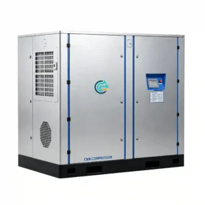
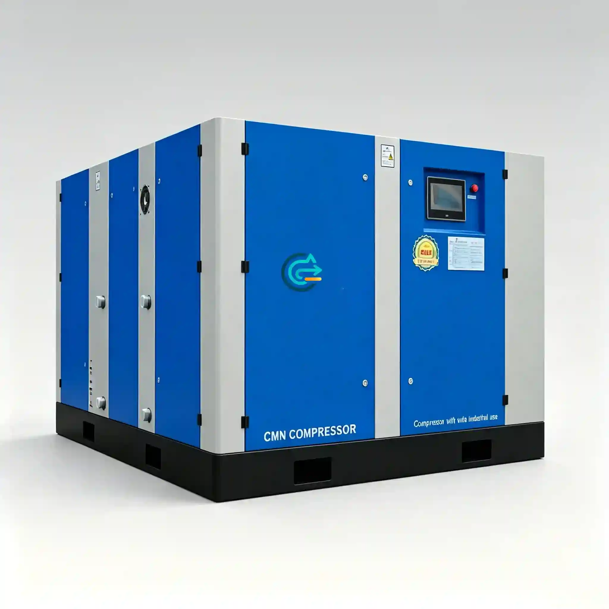
20 Bar Oil-Free Screw Compressor
Continuous-duty, oil-free rotary screw compression to 20 bar (290 psi) — engineered for processes that cannot tolerate hydrocarbon contamination in the air supply.
Primary applications: PET bottle blowing · food & beverage processing · pharmaceutical packaging · electronics clean rooms · precision machining
Why 20 Bar Compressed Air — and Why Oil-Free
When standard network pressure is not sufficient
Most factory compressed air systems operate between 7 and 10 bar. That pressure range covers pneumatic actuators, air tools, and general plant utilities. However, certain downstream processes have a higher pressure requirement that a standard utility compressor cannot meet:
- PET preform blowing requires 20–40 bar stretch-blow pressure to achieve correct wall thickness and crystallinity in the finished bottle.
- Nitrogen generation membranes and PSA systems may require elevated feed pressure to achieve target purity at rated throughput.
- High-pressure air bearings and precision pneumatic actuators in optical or semiconductor equipment specify 15–25 bar supply.
- Dense-phase powder conveying lines in pharmaceutical or food plants commonly run at 4–8 bar, but when the pipeline is long or the material is heavy, 15–20 bar becomes necessary.
A 20 bar compressor is a medium-pressure machine — it occupies the design space between a standard low-pressure industrial compressor (7–13 bar) and a high-pressure booster or reciprocating unit (40–350 bar). Rotary screw technology at this pressure range delivers better flow stability, lower noise, and longer maintenance intervals compared to reciprocating piston designs at equivalent output.
Oil-free versus oil-flooded at medium pressure
In an oil-flooded rotary screw compressor, lubricating oil is injected into the compression chamber to seal rotor clearances, remove heat of compression, and lubricate bearings. After compression, a separator removes the bulk of the oil, but aerosol carry-over typically remains in the range of 2–5 ppm. Downstream filtration can reduce this further, but not to zero — and oil aerosol that passes a saturated or bypassed filter element causes process contamination.
In an oil-free rotary screw compressor, the compression rotors operate without any lubricant contact. The resulting air output meets ISO 8573-1 Class 0 oil content classification. This is the appropriate compressor type when:
- Air contacts the product directly (food, beverage, pharmaceutical, cosmetics).
- Downstream instrumentation or sensors are sensitive to hydrocarbon fouling.
- The process generates explosive or flammable vapors, and oil mist in the air supply creates ignition risk.
- Plastic molding processes require clean air to avoid surface defects or mold contamination.
- Regulatory or customer audit requirements mandate a documented oil-free air supply.
Two-stage compression at 20 bar
Reaching 20 bar in a single screw stage would require a high compression ratio that generates excessive heat, reduces volumetric efficiency, and shortens rotor service life. The CM Series uses a two-stage oil-free screw configuration: the first stage compresses atmospheric air to an intermediate pressure (typically 4–6 bar), an intercooler removes heat of compression, and the second stage compresses the cooled air to 20 bar working pressure.
CM Series — Technical Specifications
All FAD values are measured at the compressor discharge flange at rated pressure, per ISO 1217 Annex C. Power values refer to shaft input power at full load. Ambient reference conditions: 20°C, 1 bar(a), 0% relative humidity.
| Model | Motor Power (kW) | Pressure (bar) | FAD (m³/min) | FAD (cfm approx.) | Typical Application |
|---|---|---|---|---|---|
| CM11G | 18.5 | 20 | 1.73 | ~61 | Small PET blowing lines (1–2 cavities), lab or pilot-scale clean air supply |
| CM22G | 22 | 20 | 2.10 | ~74 | 4-cavity PET blowing, pharmaceutical packaging lines, food processing units |
| CM37G | 37 | 20 | 3.30 | ~117 | 6–8 cavity PET blowing, electronics clean room supply, precision machining cells |
| CM55G | 55 | 20 | 6.20 | ~219 | High-output PET lines (12+ cavities), large-scale food/beverage plants, OEM system integration |
| Parameter | Specification |
|---|---|
| Compression type | Two-stage oil-free rotary screw |
| Oil content at discharge | ISO 8573-1 Class 0 (0 mg/m³ total oil) |
| Working pressure | 20 bar (290 psi) |
| Cooling method | Air-cooled with intercooler and aftercooler |
| Drive | Direct drive, V-belt reduction, or gearbox (model-dependent) |
| Control | PLC-based with load/unload and modulation modes |
| Inlet filtration | 3-stage inlet filter, ≤ 3 μm particulate |
| Noise level | ≤ 72 dB(A) at 1 m (full load, free-field conditions) |
| Power supply | 380/400/415 V, 3-phase, 50/60 Hz |
| Ambient operating range | +5°C to +40°C |
| Altitude limitation | Up to 1,000 m ASL standard; derated output above 1,000 m |
| Air end service interval | 8,000 hours (rotor bearing inspection) |
| Teflon coating replacement | Every 16,000–24,000 hours depending on operating duty |
Engineering Design Features
Oil-free compression chamber
The CM Series uses a dry-running two-stage screw air end. Rotor clearances are maintained by precision-ground synchronizing gears on the rotor shafts. The male and female rotors are coated with PTFE-based or PEEK-composite material to minimize contact wear during start-up transients and to provide a sealing film without liquid lubrication. Bearing lubrication is contained within sealed gearboxes that are positively isolated from the air path by shaft seals and labyrinth gaps — no crossover path exists between the lubrication circuit and the compression chamber.
This design produces compressed air that meets ISO 8573-1 Class 0 oil classification without relying on downstream oil removal filters.
Pressure stability and control
The PLC controller maintains discharge pressure within ±0.2 bar of the set point across the load range. In load/unload mode, the machine runs at full capacity when demand is present and vents the inlet valve when demand drops below the lower pressure threshold. An optional frequency-drive (VFD) variant modulates motor speed proportionally to air demand, reducing part-load power consumption by 20–35% compared to fixed-speed load/unload.
Specific power and energy consumption
At 20 bar working pressure, the CM Series achieves a measured specific power in the range of 9.8–11.2 kW/(m³/min) depending on model and load point. Accurate system sizing is important: an oversized machine operating at partial load will consume disproportionately more energy per unit of air delivered.
Maintenance access and service design
Key service access points:
- Inlet air filter: tool-free cartridge replacement, accessible from the front panel.
- Gearbox oil: sight glass and drain at floor level; oil change interval 4,000 hours.
- Intercooler and aftercooler: removable panels for annual fin cleaning.
- Condensate drains: electronic timed drains on the intercooler separator and aftercooler separator.
- Control panel: DIN-rail mounted components, labeled terminal blocks, diagnostic fault log stored in PLC non-volatile memory.
Application Areas
PET bottle blowing
PET preform stretch-blow molding requires high-pressure compressed air in two stages: a pre-blow phase at 8–12 bar, followed by a high-blow phase at 18–40 bar to achieve final bottle shape. The 20 bar output of the CM Series covers the pre-blow and initial high-blow phases for most beverage and edible-oil bottle formats. Because the air enters the PET preform directly, ISO Class 0 oil-free certification is required under most food-contact regulations (EU 10/2011, FDA 21 CFR).
Typical CM Series sizing for PET applications: 1–2 cavity machines require CM11G (1.73 m³/min); 4-cavity machines require CM22G (2.10 m³/min); 8–12 cavity machines typically match CM37G or CM55G.
Food and beverage packaging
Food packaging lines use compressed air in multiple ways: form-fill-seal machine actuation, product ejection, conveying, sealing die pressure, and direct product contact. Any air stream that may contact an exposed food surface requires oil-free classification. The CM Series provides a single compressor source for both high-pressure process air and, through a downstream pressure reducer, plant utility air at 6–8 bar.
Electronics and semiconductor manufacturing
PCB assembly, semiconductor packaging, and flat-panel display manufacturing use compressed air for component pick-and-place pneumatics, SMT adhesive dispensing, and clean-room pressurization. Hydrocarbon contamination from oil-flooded compressors causes ionic surface contamination and flux residue bonding failures. The CM Series meets ISO 8573-1 Class 0 requirements directly from the machine outlet.
Precision machining and metrology
Air gauging, air bearing spindles, and pneumatic clamping fixtures in precision machining cells require a stable, clean, dry air supply at repeatable pressure. The CM Series, paired with a refrigerant dryer (pressure dew point +3°C) and a 0.01 μm coalescing filter, provides the air quality necessary for air bearing operation and ISO/ASME gauge calibration environments.
Compressor Selection Methodology
Step 1 — Confirm working pressure
Determine the pressure required at the point of use, then add line losses:
- Pressure drop through aftercooler and dryer: 0.3–0.5 bar
- Pressure drop through distribution piping: 0.1–0.3 bar
- Pressure drop through filter assemblies at design flow: 0.2 bar per element
- Control band (load/unload differential): 1.0–1.5 bar
Each additional bar above minimum required pressure increases power consumption by approximately 4–6% at constant flow.
Step 2 — Calculate required FAD
FAD (Free Air Delivery) is the volumetric flow rate referenced to inlet conditions. To calculate from Nm³/h:
FAD (m³/min) = [Nm³/h × (T_inlet / 273.15) × (1.01325 / P_inlet)] / 60
Add a demand margin of 10–15% over calculated peak demand to account for future process additions and ambient temperature correction.
Step 3 — Confirm duty cycle
CM Series compressors are rated for continuous duty (100% load factor). If the process demand is intermittent, a receiver tank sized to 10–15 times the machine’s FAD (in liters) will buffer demand peaks. For processes that run less than 50% of each hour, a VFD-equipped variant saves approximately 25–30% motor energy compared to fixed-speed load/unload.
| Required FAD | Model | Motor Power | Notes |
|---|---|---|---|
| Up to 1.73 m³/min (61 cfm) | CM11G | 18.5 kW | Confirm ambient temperature; output reduces above 35°C |
| 1.74 – 2.10 m³/min (62–74 cfm) | CM22G | 22 kW | Most common size for 4-cavity PET lines |
| 2.11 – 3.30 m³/min (75–117 cfm) | CM37G | 37 kW | Check power supply capacity; 3-phase 37 kW requires adequate feeder sizing |
| 3.31 – 6.20 m³/min (118–219 cfm) | CM55G | 55 kW | For high-demand applications; parallel installation available for redundancy |
Frequently Asked Questions
What is a 20 bar oil-free screw compressor used for?
The primary application is PET bottle blow molding, which requires 18–22 bar air to stretch and inflate preforms. Other uses include high-pressure pneumatic conveying, membrane nitrogen generation with elevated feed pressure, air bearing spindles in precision machining, and any process where the air supply must meet ISO 8573-1 Class 0 oil content — meaning zero detectable hydrocarbon contamination in the delivered air.
How is FAD calculated, and how does it differ from nominal flow?
FAD (Free Air Delivery) is the compressor’s output flow rate referenced to ambient inlet conditions: typically atmospheric pressure (1 bar), 20°C, and 0% humidity, per ISO 1217. Nominal or rated flow figures from some manufacturers are stated at working pressure conditions. When comparing compressors, confirm all flow figures are stated as FAD per ISO 1217 Annex C, not “compressed volume at discharge pressure.” The CM Series specifications are all ISO 1217 FAD values.
What is ISO 8573-1 Class 0, and does the CM Series achieve it without downstream filters?
ISO 8573-1 Class 0 for oil requires that total oil content — including aerosol, liquid, and vapor — not exceed a level defined as more stringent than Class 1 (0.01 mg/m³). For the CM Series, Class 0 certification means zero detected oil at the compressor discharge under standard test conditions. This classification is achieved by the oil-free air end design itself, not by downstream filtration.
Can the CM Series operate in parallel for redundancy or increased flow?
Yes. Two or more CM Series units can be connected to a common high-pressure receiver and controlled by a sequencing controller or by individual pressure-band staggering. A typical parallel configuration uses a primary/standby arrangement: one machine covers base load and a second starts automatically if discharge pressure drops below the secondary set point.
How does ambient temperature affect output?
Compressor FAD is measured at a reference inlet temperature of 20°C. For every 3°C increase above the reference, FAD decreases by approximately 1% due to lower inlet air density. At 40°C ambient — the rated maximum — output is approximately 6–7% below the nameplate FAD figure. For installations in hot climates, provide adequate ventilation and confirm ambient conditions before sizing.
What is the required maintenance schedule for the CM Series?
- Every 500 hours: Inspect inlet air filter differential pressure; clean or replace if above 25 mbar drop.
- Every 2,000 hours: Inspect condensate drain operation; verify electronic drain cycle timing.
- Every 4,000 hours: Gearbox oil change; inspect cooler fins and clean.
- Every 8,000 hours: Air end rotor bearing inspection; replace rotor tip seals.
- Every 16,000–24,000 hours: Rotor coating inspection; rebush or recoat as required.
Does the 20 bar output require special pressure vessel certification for the receiver tank?
Yes. A receiver tank connected to a 20 bar compressor must be designed and tested to the applicable pressure vessel code: ASME Section VIII Division 1 (USA), Pressure Equipment Directive 2014/68/EU (European Union), AS/NZS 1200 and AS 4041 (Australia). Confirm certification requirements with a pressure equipment inspector before procurement.
What compressed air dryer type is compatible with a 20 bar oil-free compressor?
The dryer must be rated for the working pressure of the system. Options:
- Refrigerant dryer (20 bar rated): Achieves pressure dew point of +3°C. Adequate for most industrial and food processing applications.
- Desiccant dryer (20 bar rated): Required for applications needing pressure dew point below −20°C.
- Membrane dryer: Suitable for moderate flow rates and modest dew point requirements (+10°C range).
Technical Inquiry — CM Series Compressor Selection
To provide an accurate model recommendation and application review, submit your operating requirements using the parameters listed below.
Required information for compressor selection
- Working pressure required at point of use (bar or psi)
- Required FAD or process air consumption (m³/min, Nm³/h, or cfm)
- Duty cycle — continuous duty, or estimated run hours per shift
- Ambient temperature range at the installation site (°C or °F)
- Installation altitude (m or ft above sea level)
- Application description — what the air is used for
- Air purity requirement — dew point, particulate class, oil class (if specified)
- Power supply — voltage, phase, frequency
Submit your requirements by email. A compressed air systems engineer will review your application and respond with a model recommendation, performance data sheet, and dimensional drawing within 2 business days.
Response includes: recommended model, confirmed FAD at your ambient conditions, specific power figure, dimensional drawing, and suggested downstream equipment (dryer, receiver, filtration).