Description
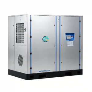
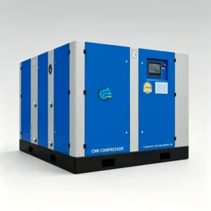
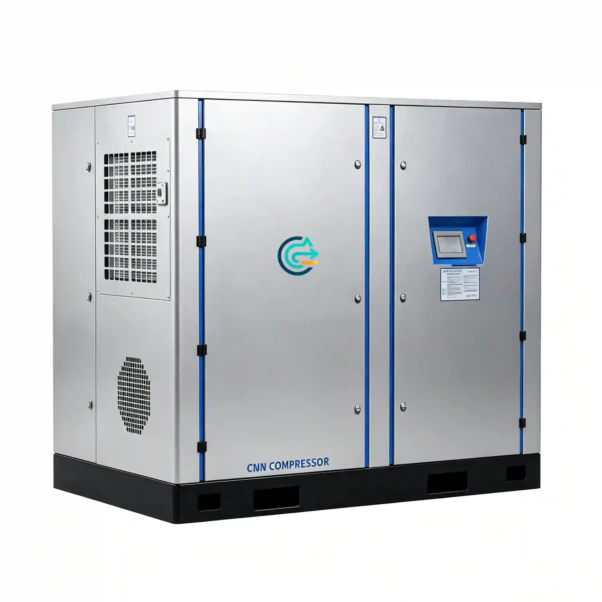
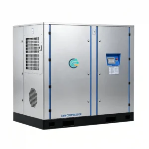
Medium Pressure Oil Screw Compressor — CMN/G Series
Two-stage micro-oil rotary screw compression at 20–40 bar working pressure — designed for general manufacturing, factory compressed air systems, and industrial production lines where high-flow medium-pressure air is required and ISO Class 0 oil-free certification is not a process requirement.
- Working Pressure: 20 – 40 bar
- Motor Power Range: 75 – 150 kW
- FAD Capacity Range: 6.3 – 14.0 m³/min
- Models: CN75G · CN90G · CN110GV · CN130GV · CN150GV
- Primary Applications: general manufacturing · factory compressed air networks · industrial production lines · pneumatic conveying · process air utilities
Oil-Free versus Micro-Oil Screw Compressor — Engineering Comparison
What is a micro-oil screw compressor?
A micro-oil (oil-injected) rotary screw compressor uses a controlled quantity of lubricating oil injected directly into the compression chamber. The oil serves three functions simultaneously: it seals the clearance between male and female rotors, removing the need for precision dry-running rotor coatings; it absorbs the heat of compression, allowing a higher compression ratio per stage without thermal damage; and it lubricates the rotor bearings and timing gears. After compression, the oil-air mixture passes through a high-efficiency oil separator that removes the bulk of the oil — residual carry-over in the delivered compressed air is typically in the range of 1–5 ppm by mass.
The term “micro-oil” refers to this residual content after separation — it is not zero, but it is low enough for the vast majority of industrial utility air applications where product contact is not involved.
What is an oil-free screw compressor?
An oil-free rotary screw compressor uses precision synchronizing gears to maintain rotor clearances without any lubricant in the compression chamber. The rotors are coated with PTFE-based or PEEK-composite material for start-up wear resistance. The gearbox and bearing lubrication circuit is completely isolated from the air path by shaft seals and labyrinth gaps. The delivered compressed air meets ISO 8573-1 Class 0 — zero detected oil content at the machine discharge, without relying on downstream filtration.
Which type is appropriate for your application?
The decision between oil-free and micro-oil at medium pressure (20–40 bar) comes down to the air purity requirement at the point of use, not a general preference. Micro-oil compressors are the correct specification when:
- The compressed air does not contact a food, pharmaceutical, or beverage product directly.
- The process does not involve sensitive instrumentation that is affected by hydrocarbon aerosol.
- The operating environment does not involve explosive or flammable vapors where oil mist creates an ignition risk.
- ISO 8573-1 Class 0 is not specified by a customer, regulator, or process engineer.
- The priority is maximizing flow capacity per unit of motor power at the lowest capital and operating cost.
For general manufacturing compressed air systems — pneumatic tooling, actuator networks, conveying, and production line utilities — micro-oil compressed air at 1–5 ppm residual content is technically adequate and poses no process or safety issue. The CMN/G Series is designed for exactly this application profile.
Efficiency and operating cost comparison
At equivalent motor power and discharge pressure, a micro-oil screw compressor delivers higher FAD than an oil-free machine of the same power class. The injected oil provides superior rotor-tip sealing compared to dry-running PTFE or PEEK coatings, particularly at the elevated pressure ratios required to reach 20–40 bar. This results in lower internal volumetric leakage and higher compression efficiency. Specific power (kW per m³/min) for the CMN/G Series at 20–40 bar is typically 8–12% lower than equivalent oil-free machines at the same pressure, which represents a meaningful energy cost difference at 75–150 kW continuous duty.
Capital cost of a micro-oil machine is also lower than an oil-free machine at equivalent power and pressure, primarily because the oil-free design requires precision-ground synchronizing gears, tighter manufacturing tolerances on rotor profiles, and specialized coating materials that add cost. Maintenance cost for micro-oil machines is centered on oil separator element replacement (typically every 3,000–4,000 hours) and oil changes (every 2,000 hours), rather than the rotor coating inspections and rebush cycles required on oil-free machines at 16,000–24,000 hour intervals.
CMN/G Series — Technical Specifications
FAD values are measured at the compressor discharge flange per ISO 1217 Annex C. Reference conditions: 20°C inlet temperature, 1 bar(a) inlet pressure, 0% relative humidity. VFD models (CN110GV, CN130GV, CN150GV) show FAD at rated speed; actual output varies across the VFD operating range.
| Model | Motor Power (kW) | Pressure Range (bar) | FAD (m³/min) | FAD (cfm approx.) | Drive | Typical Application |
|---|---|---|---|---|---|---|
| CN75G | 75 | 20 – 40 | 6.3 | ~222 | Fixed speed | Medium-scale factory air, pneumatic conveying, production line utilities |
| CN90G | 90 | 20 – 40 | 8.2 | ~290 | Fixed speed | Large factory compressed air networks, continuous production duty |
| CN110GV | 110 | 20 – 40 | 13.3 | ~470 | VFD | Variable-demand industrial plants, multi-shift manufacturing |
| CN130GV | 75 | 20 – 40 | 10.2 – 14.0 | ~360 – 494 | VFD | Variable-demand systems requiring wide FAD range at medium pressure |
| CN150GV | 75 | 20 – 40 | 13.5 | ~477 | VFD | High-flow industrial base-load with demand modulation capability |
| Parameter | Specification |
|---|---|
| Compression type | Two-stage oil-injected rotary screw |
| Oil content at discharge (after separator) | 1 – 5 ppm by mass (ISO 8573-1 Class 1–2 for oil, with downstream coalescing filter) |
| Working pressure range | 20 – 40 bar (290 – 580 psi) |
| Cooling method | Air-cooled intercooler and aftercooler (standard); water-cooled on request |
| Lubrication oil type | Synthetic compressor oil, ISO VG 46 or VG 68 (manufacturer specification) |
| Oil separator efficiency | ≥ 99.9% oil removal at rated flow and pressure |
| Oil separator element service interval | 3,000 – 4,000 hours (replace at differential pressure indicator threshold) |
| Compressor oil change interval | 2,000 hours (synthetic oil) |
| Control system | PLC-based; load/unload (fixed speed) or continuous modulation (VFD models) |
| Inlet filtration | Dry-type panel filter, ≤ 5 μm particulate; replaceable element |
| Noise level | ≤ 76 dB(A) at 1 m (full load, free-field conditions) |
| Power supply | 380/400/415 V, 3-phase, 50/60 Hz |
| Ambient operating range | +5°C to +40°C |
| Altitude limit (standard) | 1,000 m ASL; derated output above — consult engineering |
| Protection rating | IP54 standard enclosure |
| Feature | Micro-Oil Screw (CMN/G Series) | Oil-Free Screw (CM/G Series) |
|---|---|---|
| Oil content at discharge | 1 – 5 ppm (with downstream filter) | ISO 8573-1 Class 0 (zero detected) |
| Specific power at 20–40 bar | Lower by 8–12% at equivalent pressure | Higher — tighter rotor clearances required |
| Capital cost at equivalent power | Lower | Higher (precision gears, rotor coatings) |
| Primary maintenance item | Oil separator element (3,000–4,000 h); oil change (2,000 h) | Rotor coating inspection (16,000–24,000 h); gearbox oil (4,000 h) |
| Rotor design | Oil-sealed; standard rotor profile tolerances | Dry-running; PTFE/PEEK coated; precision synchronizing gears |
| Suitable for food/pharma direct contact | No — residual oil present | Yes — Class 0 oil-free |
| Suitable for general manufacturing utilities | Yes — standard specification | Yes — over-specified for most utility applications |
| Operating cost over 10 years | Lower energy + lower capital = lower TCO for utility air | Higher capital; lower filter element cost vs. oil-flooded + downstream filtration |
Application Areas
General manufacturing compressed air
General manufacturing facilities — metal fabrication shops, plastic injection molding plants, rubber processing operations, and assembly facilities — use compressed air at medium pressure for a range of utility applications: pneumatic clamping and fixturing, press actuation, blow-off stations, material conveying, and air-powered tooling. In these applications, the compressed air does not contact the manufactured product directly, and residual oil content at 1–5 ppm after a standard coalescing filter is within the acceptable range for all pneumatic equipment specifications.
At 20–40 bar, the CMN/G Series provides a single compressor source that supplies both high-pressure process air (for applications such as air-powered presses or high-pressure actuators) and, through a pressure regulator and receiver, the standard 7–10 bar plant utility network. This eliminates the need for separate compressor systems at different pressure levels.
Factory compressed air networks
Large factory compressed air networks serving multiple production departments simultaneously require a compressor with sufficient FAD to sustain header pressure across all distribution branches under simultaneous peak demand. At 110–150 kW and 13–14 m³/min FAD, the CN110GV, CN130GV, and CN150GV are sized for factories with total compressed air demand in the range that would otherwise require three to four standard 7-bar compressors operating in parallel.
VFD-equipped models in the CMN/G Series maintain header pressure within a tight band as demand shifts between shifts and production states, without the pressure spikes and load/unload cycling associated with fixed-speed machines serving a variable-demand network. This is particularly relevant in multi-product factories where compressed air demand varies significantly between production runs.
Industrial production lines
Continuous production lines in automotive components, consumer goods, building materials, and packaging use compressed air continuously across multiple stations simultaneously. The defining characteristic of production line air demand is that it is relatively predictable and consistent within a shift — which makes fixed-speed CMN/G models (CN75G, CN90G) well-suited as base-load machines, with a VFD model as a trim machine to handle demand variation between production changeovers.
At 20–40 bar working pressure, the CMN/G Series is also appropriate for production lines that include pneumatic press operations, high-pressure clamping, or air-powered forming tools that require pressure above the standard utility 7–10 bar range, without the capital and operating cost premium of an oil-free machine.
Pneumatic conveying systems
Dense-phase and dilute-phase pneumatic conveying systems for granular materials (plastic pellets, food grains, cement, mineral powder) require sustained compressed air flow at pressures that vary from 3 bar (dilute phase, short distance) to 20–35 bar (dense phase, long distance or high-bulk-density materials). The CMN/G Series at 20–40 bar covers the pressure requirement for dense-phase conveying applications in plastics, building materials, and bulk chemical handling where oil content in the conveying air is not a product contamination concern.
Compressor Selection Guide
Step 1 — Confirm air purity requirement
Before selecting a micro-oil compressor, confirm with the process engineer or facility manager that ISO 8573-1 Class 0 oil-free air is not required by any downstream process, equipment manufacturer specification, customer audit requirement, or regulatory standard. If Class 0 is required at any point in the compressed air system, an oil-free compressor (CM/G Series) is the correct specification — a micro-oil machine with downstream filtration cannot achieve Class 0.
If the air purity requirement is ISO 8573-1 Class 1–2 for oil (achievable with a downstream coalescing filter on the CMN/G discharge), the micro-oil specification is appropriate and the CMN/G Series is the more cost-effective choice.
Step 2 — Determine required working pressure
Establish the pressure required at the highest-pressure point of use in the system, then add line losses between the compressor discharge and that point:
- Aftercooler and oil separator pressure drop: 0.5–0.8 bar
- Downstream coalescing filter at design flow: 0.2–0.3 bar per element
- Piping distribution losses (properly sized header): 0.1–0.3 bar
- Load/unload control band (fixed-speed models): 1.5–2.0 bar
The CMN/G Series is configurable across the 20–40 bar range — specify your required discharge pressure at time of order so the correct internal compression ratio and safety valve settings are supplied.
Step 3 — Calculate required FAD
Calculate total plant FAD demand using a diversity factor of 0.6–0.75 applied to the nameplate consumption sum of all pneumatic consumers, unless simultaneous peak demand is a confirmed operating condition. Add 10–15% margin for future additions and for ambient temperature derating above 20°C reference (approximately 1% FAD reduction per 3°C above reference).
Step 4 — Fixed speed or VFD
Fixed-speed models (CN75G, CN90G) are appropriate for plants with consistent, predictable air demand where the compressor will run at near-full load throughout the operating period. VFD models (CN110GV, CN130GV, CN150GV) are appropriate when demand varies significantly between production states, shifts, or product changeovers. At 50% demand, a VFD unit saves approximately 25–30% motor energy compared to a fixed-speed machine of equivalent rated FAD operating in load/unload mode.
| Required FAD at 20–40 bar | Model | Power (kW) | Drive | Notes |
|---|---|---|---|---|
| Up to 6.3 m³/min (222 cfm) | CN75G | 75 | Fixed | Medium-scale factory; confirm ambient temperature above 35°C |
| 6.4 – 8.2 m³/min (223–290 cfm) | CN90G | 90 | Fixed | Large factory base-load; check 3-phase feeder sizing for 90 kW |
| 8.3 – 13.3 m³/min (291–470 cfm) | CN110GV | 110 | VFD | Variable-demand industrial; VFD provides demand-matched output |
| 10.2 – 14.0 m³/min (360–494 cfm) variable | CN130GV | 75 | VFD | Wide FAD range; confirm exact pressure-FAD curve with engineering |
| Up to 13.5 m³/min (477 cfm) | CN150GV | 75 | VFD | High-flow base-load with modulation; confirm motor power rating |
Frequently Asked Questions
What is the difference between a micro-oil and an oil-free screw compressor at medium pressure?
A micro-oil (oil-injected) screw compressor introduces lubricating oil into the compression chamber to seal rotor clearances and remove heat of compression. After compression, a separator removes the bulk of the oil, leaving residual content of 1–5 ppm in the delivered air. An oil-free screw compressor operates with no lubricant in the compression chamber — the compression rotors use precision synchronizing gears to maintain clearance and PTFE or PEEK coatings for sealing. Oil-free machines deliver ISO 8573-1 Class 0 air at the discharge; micro-oil machines can achieve Class 1–2 with a downstream coalescing filter. For general manufacturing and factory utility air where the compressed air does not contact a product, a micro-oil machine is technically adequate and offers lower capital cost and higher efficiency at equivalent power.
What residual oil content should I expect in the compressed air from the CMN/G Series?
Directly at the oil separator discharge, residual oil content is typically 1–5 ppm by mass under normal operating conditions — new separator element, correct operating temperature (above oil dewpoint), and rated flow. This corresponds to ISO 8573-1 Class 2 for oil aerosol. With a downstream 1 μm coalescing filter, residual content reduces to approximately 0.1 ppm (Class 1). With a 0.01 μm high-efficiency coalescing filter, residual content reduces to approximately 0.01 ppm (at the lower limit of Class 1). These figures apply at normal operating temperature — at low load or cold start, oil carry-over increases temporarily until the separator reaches operating temperature. Class 0 cannot be achieved with a micro-oil machine regardless of downstream filtration.
Can the CMN/G Series be used for PET bottle blowing?
Not as the primary high-blow air supply if the PET bottles are for food or beverage contact. PET preform stretch-blow molding requires air that contacts the interior surface of the finished bottle — this constitutes food-contact air under EU Regulation 10/2011 and FDA 21 CFR, which requires ISO 8573-1 Class 0 oil-free compressed air. A micro-oil machine producing 1–5 ppm residual oil, even with downstream filtration, does not meet Class 0 and is not compliant for food-contact bottle blowing. For PET blowing, specify the CM/G Series oil-free compressor. The CMN/G Series can be used for non-contact pneumatic utility air in the same facility (actuators, conveying, general plant utilities) if those circuits are kept separate from the blowing air circuit.
How often does the oil separator element need to be replaced?
Under normal operating conditions — correct compressor oil type, operating temperature above the minimum threshold, inlet air not contaminated with water vapor or aggressive chemicals — the oil separator element service life is 3,000–4,000 hours. The PLC monitors differential pressure across the separator element and alerts the operator when pressure drop exceeds the replacement threshold (typically 0.8–1.0 bar differential). Operating above this threshold reduces separator efficiency (oil carry-over increases), reduces compressor output due to higher backpressure on the separator, and increases oil consumption. Replace the element at the differential pressure trigger, not on a fixed calendar basis. In hot or humid ambient conditions, or where the compressor oil is degraded, separator life may be shorter.
What type of downstream filtration is required with a micro-oil compressor?
For general factory utility air (ISO 8573-1 Class 1–2), a single 1 μm coalescing filter downstream of the aftercooler and receiver is the standard configuration. For instrument air or precision pneumatic applications requiring Class 1 oil content (≤ 0.01 mg/m³), a two-stage filter assembly — a 1 μm coalescing pre-filter followed by a 0.01 μm high-efficiency coalescing filter — is required. An activated-carbon adsorption filter can be added if oil vapor (not aerosol) must also be reduced below 0.003 mg/m³ for sensitive instrumentation. Note that all downstream filter elements must be rated for the working pressure of the system (20–40 bar) — standard 7–10 bar filter assemblies must not be used.
What maintenance is required for the CMN/G Series compressor?
- Every 500 hours: Inspect inlet air filter differential pressure; replace element if pressure drop exceeds specification. In dusty environments, shorten to 200–300 hours.
- Every 1,000 hours: Check compressor oil level; top up with the same oil grade if below minimum mark.
- Every 2,000 hours: Compressor oil change (synthetic oil). Inspect oil cooler and aftercooler fin surfaces; clean with compressed air if fouled.
- Every 3,000–4,000 hours: Replace oil separator element when differential pressure indicator triggers replacement threshold.
- Every 4,000 hours: Inspect drive belts or coupling for wear; replace as required. Check all temperature and pressure sensors against calibrated reference.
- Every 8,000 hours: Bearing inspection on the air end and motor. Verify inlet valve and unloader mechanism operation.
Does a micro-oil compressor at 20–40 bar require a special receiver tank certification?
Yes — the pressure vessel (receiver) must be certified to the applicable national standard for the working pressure. At 20–40 bar, this is a higher pressure class than a standard 7–10 bar factory air receiver and requires a different vessel specification. In the United States: ASME Section VIII Division 1, MAWP stamped at or above the compressor maximum working pressure. In the European Union: Pressure Equipment Directive 2014/68/EU, CE marked with Notified Body inspection for the applicable pressure-volume category. In Australia: AS/NZS 1200 and AS 4041. The receiver must also be equipped with a pressure relief valve set no higher than MAWP, a drain valve, and a pressure gauge — all rated for the working pressure. Confirm receiver certification requirements with a local pressure equipment inspector before procurement.
Can the CMN/G Series be operated in parallel with a standard 7–10 bar utility compressor on the same header?
Not directly — a 20–40 bar compressor and a 7–10 bar compressor cannot share a common receiver because the higher-pressure machine would over-pressurize the lower-pressure machine’s components and relief valves. The correct architecture for a plant requiring both pressure levels is to operate the CMN/G Series on a dedicated 20–40 bar distribution circuit, then use a pressure regulator to reduce the supply to a 7–10 bar secondary circuit fed from the high-pressure receiver. This provides both pressure levels from a single compressor, eliminates the need for a separate low-pressure compressor, and ensures all components in the 7–10 bar circuit are not exposed to pressures above their rated design pressure. Size the pressure regulator for the maximum expected flow to the 7–10 bar circuit to avoid excessive pressure drop across the regulator at peak demand.
Technical Inquiry — CMN/G Series Medium Pressure Compressor Selection
Submit your plant operating requirements using the parameters below. A compressed air systems engineer will review your application and respond with a model recommendation, confirmed FAD at your site conditions, downstream filtration sizing, and dimensional drawing within 2 business days.
Required information
- Required working pressure at point of use — bar or psi
- Required FAD or total plant air consumption — m³/min, Nm³/h, or cfm
- Air purity requirement — confirm whether ISO 8573-1 Class 0 oil-free is specified, or state the acceptable oil content class
- Application description — how the compressed air is used and what equipment it serves
- Duty cycle — continuous operation, or estimated run hours per shift
- Demand profile — constant load, or variable (provide estimated min/max demand if variable)
- Site ambient temperature range — minimum and maximum, °C or °F
- Installation altitude — meters or feet above sea level
- Power supply — voltage, phases, frequency
- Existing compressed air infrastructure — receiver tank size, distribution piping pressure rating, existing filtration
Email: [email protected]
Response includes: model recommendation, confirmed FAD at your ambient conditions, downstream filtration specification, pressure vessel sizing guidance, and dimensional drawing for plant layout.