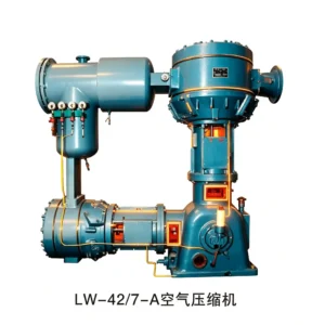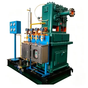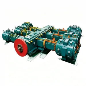
Description
Two-Column Two-Stage · Oil-Free · 0.55 – 0.80 MPa
DW Series Oil-Free Air Compressors
Large-capacity, two-column two-stage reciprocating air compressors engineered for continuous-duty industrial processes requiring ISO 8573-1 Class 0 air purity. Available from 48 m³/min to 130 m³/min, pressure-rated at 0.55 – 0.80 MPa, with frame weights from 5.5 t to 18 t and power draw from 280 kW to 800 kW.
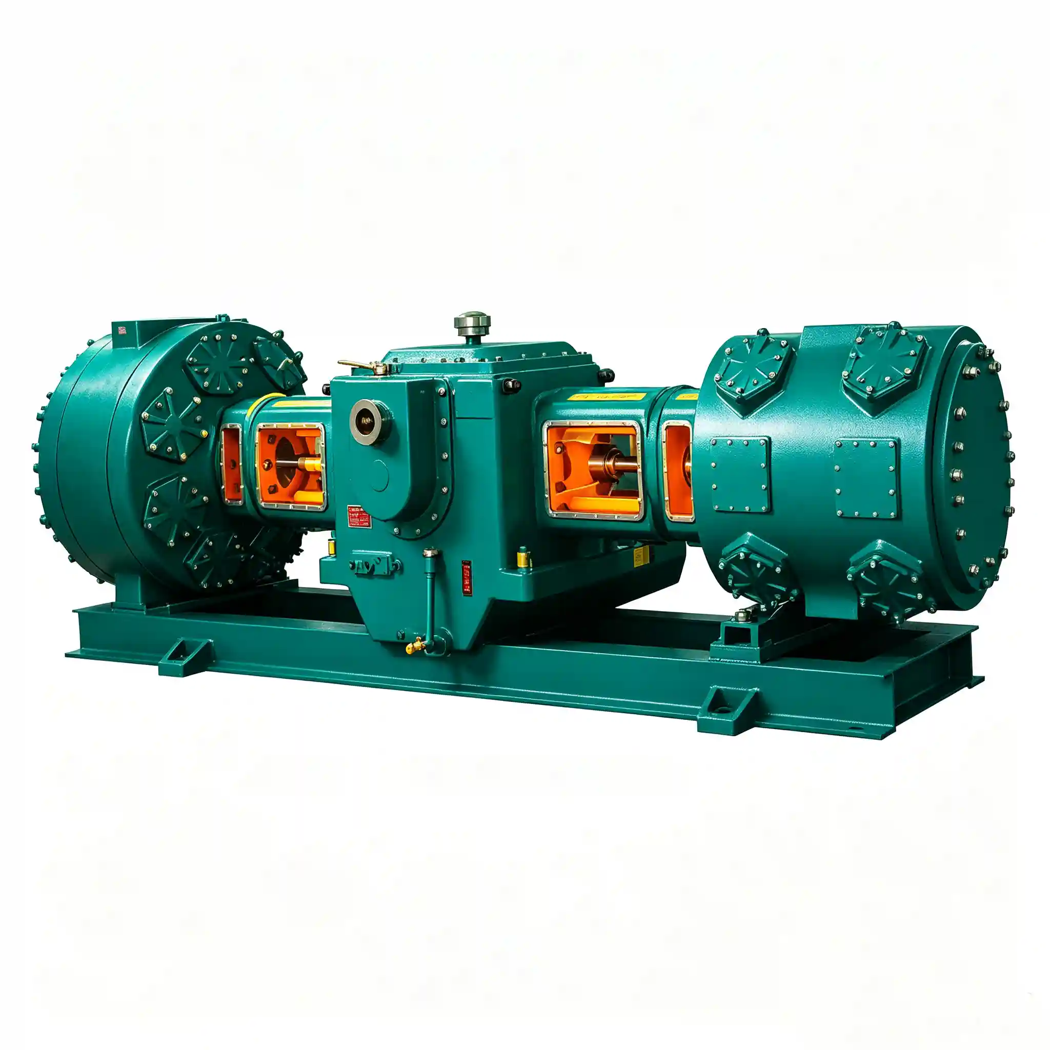
DW-130/8-A — 130 m³/min · 0.80 MPa · 800 kW · 6k或10k V
DW Series: Heavy-Duty Oil-Free Reciprocating Compressors for Large-Scale Industrial Air Supply
The DW series covers the widest flow range in the Ever-Power oil-free lineup, spanning capacities from 48 m³/min (DW-48/5.6-A) up to 130 m³/min (DW-130/8-A). All units share a two-column, two-stage reciprocating architecture configured to achieve the thermodynamic efficiency gains of staged compression while maintaining the footprint discipline demanded by large fixed installations.
Cylinder bores and piston rings are manufactured without lubrication media in the gas path, satisfying the contamination requirements of DIN EN 1012-1 and ISO 8573-1 Class 0 (oil aerosol ≤ 0.01 mg/m³, particle count Class 1). This makes the DW series suitable for pharmaceutical manufacturing, food-grade pneumatic conveying, PET bottle blowing, and large fermentation plant aeration — applications where hydrocarbon carryover would compromise product integrity or process chemistry.
The DW-200, DW-220, DW-260, and DW-300 class machines (four-column two-stage, HW series) share the same design philosophy but are documented separately. This page addresses DW-designated models specifically: the two-column units rated at 0.55 – 0.80 MPa, whose 6 kV or 10 kV electrical configurations are suited to medium-voltage industrial distribution networks.
Technical Design Features
Two-Stage Compression
Inter-stage cooling reduces the discharge temperature of the first stage before the gas enters the high-pressure cylinder, cutting specific power consumption compared to single-stage designs at equivalent pressure ratios. Cooler gas entering stage two reduces volumetric loss and slows mechanical wear on piston rings and valve seats.
Oil-Free Gas Path
PTFE-lined compression rings and guide rings eliminate the need for cylinder lubrication oil, delivering oil-free discharge air compliant with ISO 8573-1 Class 0. The crankcase remains fully lubricated through a separate sealed oil circuit that never contacts the process gas stream.
Medium-Voltage Drive
DW units above 280 kW are wired for 6 kV or 10 kV supply, allowing direct connection to plant medium-voltage buses without additional step-down transformers. This reduces infrastructure cost and improves overall power-factor performance for large industrial facilities.
Heavy-Frame Construction
Cast-iron cylinder blocks and a forged-steel crankshaft—material grade 42CrMo4 per DIN EN 10083-3—provide the structural rigidity required for 24/7 duty cycles. The DW-130/8-A, at 800 kW and 18 t, is rated for continuous operation in cement, chemical, and power-generation plant environments.
DW Series — Full Technical Specifications
| Model | Pattern | Capacity (m³/min) | Discharge Pressure (MPa) | Compressor Size L×W×H (mm) | Weight (t) | Power (kW) | Voltage (V) |
|---|---|---|---|---|---|---|---|
| DW-112/5.5-A | 二列二级 | 112 | 0.55 | 5500×3540×2720 | 13.00 | 550 | 6k or 10k |
| DW-48/5.6-A | 二列二级 | 48 | 0.56 | 2890×1600×2198 | 5.50 | 280 | 380/6k or 10k |
| DW-86/5.6-A | 二列二级 | 86 | 0.56 | 5456×3518×2535 | 13.00 | 500 | 6k or 10k |
| DW-130/5.6-A | 二列二级 | 130 | 0.56 | 5370×3540×2660 | 13.00 | 680 | 6k or 10k |
| DW-100/6-A | 二列二级 | 100 | 0.60 | 5456×3518×2535 | 13.00 | 550 | 6k or 10k |
| DW-120/7-A | 二列二级 | 120 | 0.70 | 5500×3518×2535 | 13.50 | 650 | 6k or 10k |
| DW-60/7-A | 二列二级 | 60 | 0.70 | 5500×1450×2180 | 6.00 | 350 | 6k or 10k |
| DW-75/8-A | 二列二级 | 75 | 0.80 | 5456×3518×2535 | 13.00 | 450 | 6k or 10k |
| DW-80/8-A | 二列二级 | 80 | 0.80 | 5456×3518×2660 | 13.00 | 500 | 6k or 10k |
| DW-85/8-A | 二列二级 | 85 | 0.80 | 5456×3518×2535 | 13.00 | 500 | 6k or 10k |
| DW-90/8-A | 二列二级 | 90 | 0.80 | 5440×3518×2620 | 13.00 | 550 | 6k or 10k |
| DW-95/8-A | 二列二级 | 95 | 0.80 | 5456×3518×2535 | 13.00 | 550 | 6k or 10k |
| DW-100/8-A | 二列二级 | 100 | 0.80 | 5456×3518×2535 | 13.00 | 600 | 6k or 10k |
| DW-110/8-A | 二列二级 | 110 | 0.80 | 5500×3500×2535 | 13.00 | 630 | 6k or 10k |
| DW-130/8-A | 二列二级 | 130 | 0.80 | 6000×3640×3000 | 18.00 | 800 | 6k or 10k |
| DW-150/8-A | 二列二级 | 150 | 0.80 | 6000×3640×3000 | 19.00 | 900 | 6k or 10k |
* Custom units with motor ratings from 11 kW to 2000 kW are available on request per DIN EN 1012-1.
Application Areas
The DW series is specified wherever volume flow above 60 m³/min and confirmed oil-free output are both non-negotiable. Documented deployment sectors include:
Kiln aeration, pneumatic raw-meal conveying at 0.56 – 0.80 MPa
Instrument air, valve actuation, flue-gas desulphurisation
Reactor aeration, stripper gas, pneumatic transfer (Class 0 required)
High-pressure preform stretching, 0.56 – 0.80 MPa process air
Sterile aeration for pharmaceutical API bioreactors
Frequently Asked Questions
What is the oil carryover specification for DW series compressors?
The DW series delivers oil-free air meeting ISO 8573-1 Class 0 — meaning total oil content (aerosol + vapour + liquid) is verified at ≤ 0.01 mg/m³ at rated conditions. The PTFE piston rings and guide rings function without lubrication within the gas-handling bore, and the crankcase oil circuit is physically separated from all process flow paths.
Which DW model suits a 90 m³/min air demand at 0.8 MPa?
The DW-90/8-A is rated precisely at 90 m³/min, 0.80 MPa, 550 kW — footprint 5440 × 3518 × 2620 mm, 13 t. If modest reserve capacity is preferable, the DW-95/8-A at 95 m³/min and 550 kW shares an almost identical frame envelope (5456 × 3518 × 2535 mm) and the same 6 kV / 10 kV electrical configuration.
Can custom motor ratings be accommodated for two-column DW units?
Yes. The manufacturer supports custom engineering for oil-free two-column and air-booster compressors with motor ratings between 11 kW and 2000 kW per user specifications. Lead time and compliance documentation (CE marking, GB 150 pressure-vessel certification) must be confirmed at the time of order placement.
What maintenance interval is typical for the two-stage reciprocating gas path?
PTFE piston ring replacement intervals are typically 4,000 – 6,000 operating hours under clean intake conditions (inlet filtration ≥ F7 per EN 779). Valve-plate inspection is recommended at 8,000 hours. Crankcase oil change intervals follow the motor-bearing manufacturer’s specification, generally 2,000 – 4,000 hours depending on ambient temperature and humidity.
Request a Technical Quotation for DW Series Compressors
Provide your required flow rate (m³/min), discharge pressure (MPa), and available voltage, and receive a model recommendation with dimensional drawings within 24 hours.