Description
Four-Column Two-Stage · Oil-Free · 0.80 MPa · 200 – 300 m³/min
HW Series Heavy-Duty Oil-Free Air Compressors
Four-column, two-stage reciprocating compressors rated at 200 – 300 m³/min and 0.80 MPa, with installed motor power from 1200 kW to 1800 kW. The HW series addresses the largest continuous-duty compressed air demands in cement, mining, petrochemical, and power generation infrastructure — where no comparable rotary technology reliably meets both the volume and Class 0 purity requirements simultaneously.
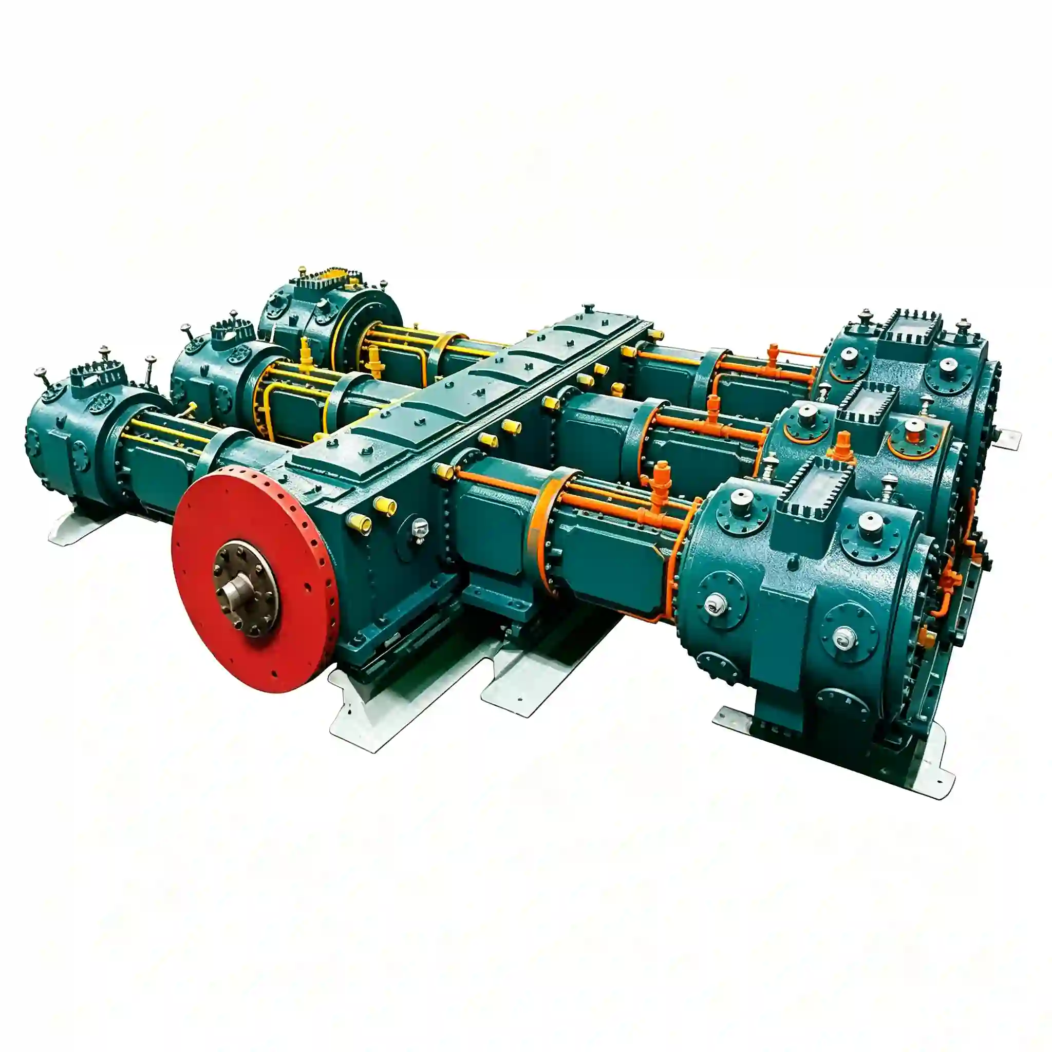
HW Series — Four-column two-stage oil-free compressors, 200 – 300 m³/min at 0.80 MPa
HW Series: Large-Scale Four-Column Oil-Free Compressors for High-Volume Industrial Air Supply
The HW series represents the highest-output tier of the Ever-Power oil-free reciprocating range. Four models — HW-200/8-A, HW-220/8-A, HW-260/8-A, and HW-300/8-A — span 200 to 300 m³/min at a fixed discharge pressure of 0.80 MPa, with motor ratings from 1200 kW to 1800 kW and machine weights from 26 t to 40 t. These are among the largest oil-free reciprocating compressors produced in the Chinese industrial compressor sector under the ever-power brand architecture.
The four-column configuration — four working cylinders arranged symmetrically around the crankshaft — provides superior primary force balance relative to two-column machines at equivalent piston displacement. This reduces transmitted vibration into the foundation structure, which is a critical design constraint for large facilities where compressor vibration can affect adjacent precision equipment, instrumented pipelines, or structural integrity of machine-room floors.
All HW models operate at 6 kV or 10 kV and are designed for direct connection to high-capacity medium-voltage switchgear, as would be specified under IEC 60439-1 for large industrial installations. The gas path remains oil-free — PTFE composite piston rings and guide elements isolate the crankcase oil circuit completely — producing ISO 8573-1 Class 0 discharge air for process requirements that cannot accept hydrocarbon contamination at any concentration.
Technical Design Features
Four-Column Balanced Architecture
The four-cylinder layout achieves a higher degree of primary and secondary force balance than two-column alternatives at the same displacement, reducing foundation loading and transmitted structure-borne vibration. For HW-300/8-A at 40 t and 1800 kW, the crankshaft is manufactured from forged alloy steel (42CrMo4, DIN EN 10083-3) with precision-ground journals held to ISO 286-1 IT6 tolerance class.
Medium-Voltage 6 kV / 10 kV Drive
At 1200 – 1800 kW, the HW series operates exclusively on 6 kV or 10 kV medium-voltage supply. This eliminates the resistive losses and transformer costs associated with step-down from MV to LV for large-motor drives. Motor efficiency at these power levels is typically ≥ 96.0% (IE3 equivalent per IEC 60034-30-1) when ordered with premium-efficiency windings.
ISO 8573-1 Class 0 Oil-Free Output
PTFE composite rings in each of the four cylinders maintain complete separation of the lubricated crankcase from the gas-handling bore. Total oil in the discharge stream is verified at ≤ 0.01 mg/m³. At 200 – 300 m³/min volume output, the HW series delivers this purity class at a throughput unmatched by comparable oil-free rotary screw or centrifugal machines in this pressure range.
Two-Stage Inter-Cooling
First-stage discharge gas is cooled before entering the high-pressure cylinders, reducing specific compression work and limiting thermal stress on valve components. At the HW scale, inter-cooler design is critical: the cooler’s heat-rejection surface must be sized for continuous operation in ambient temperatures up to 45 °C in hot-climate export markets, including northern Australia, the Middle East, and tropical South America.
HW Series — Technical Specifications
| Model | Pattern | Capacity (m³/min) | Discharge Pressure (MPa) | Compressor Size L×W×H (mm) | Weight (t) | Power (kW) | Voltage (V) |
|---|---|---|---|---|---|---|---|
| HW-200/8-A | 四列二级 | 200 | 0.80 | 5456 × 6000 × 2535 | 26.00 | 1200 | 6k or 10k |
| HW-220/8-A | 四列二级 | 220 | 0.80 | 5500 × 6400 × 2535 | 26.00 | 1250 | 6k or 10k |
| HW-260/8-A | 四列二级 | 260 | 0.80 | 6000 × 8500 × 3000 | 35.00 | 1600 | 6k or 10k |
| HW-300/8-A | 四列二级 | 300 | 0.80 | 6000 × 8500 × 3000 | 40.00 | 1800 | 6k or 10k |
* All HW models operate at 6 kV or 10 kV only. Site MV switchgear, cable sizing, and protection relay coordination must be completed by a qualified electrical engineer to IEC 60909 short-circuit current standards. Custom configurations up to 2000 kW available on request.
Foundation & Civil Engineering Considerations
HW machines at 26 – 40 t impose significant static and dynamic loads on the civil foundation. The following data, extracted from the manufacturer’s specification table, should be provided to the structural engineer at concept design stage:
| Model | Machine Weight (t) | Footprint L×W (mm) | Height (mm) | Motor Power (kW) |
|---|---|---|---|---|
| HW-200/8-A | 26.00 | 5456 × 6000 | 2535 | 1200 |
| HW-220/8-A | 26.00 | 5500 × 6400 | 2535 | 1250 |
| HW-260/8-A | 35.00 | 6000 × 8500 | 3000 | 1600 |
| HW-300/8-A | 40.00 | 6000 × 8500 | 3000 | 1800 |
Dynamic unbalanced forces and anchor bolt loads must be confirmed with the manufacturer’s foundation drawing package before civil works commence. Anti-vibration mounts may be specified to reduce transmitted vibration below ISO 10816-6 acceptance limits for large reciprocating machinery.
Application Sectors
The HW series is specified for the highest continuous-demand industrial air applications where 200 – 300 m³/min must be supplied at 0.80 MPa with guaranteed oil-free purity. Proven deployment sectors:
Kiln gas seal air, pneumatic raw-meal and clinker conveying at sustained 200+ m³/min
Instrument air header supply, ESP rapper actuation, ash conveying at multiple distribution points
Plant air for valve actuation, reactor aeration — Class 0 required to prevent catalyst contamination
High-volume sterile aeration for large-bioreactor pharmaceutical API production
Froth flotation air supply, pneumatic conveying of mineral fines at high sustained flow
Frequently Asked Questions
Why choose a four-column reciprocating compressor over a large oil-free screw or centrifugal at 200 – 300 m³/min?
Oil-free screw compressors at 0.80 MPa in the 200 m³/min class involve significant intercooling and multiple compression stages with rotor tip speeds that impose demanding tolerances on the air-gap between rotors, resulting in higher maintenance sensitivity. Centrifugal (dynamic) compressors at 0.80 MPa face surge risk at part-load and are generally more suited to pressures above 2.0 MPa for efficient pressure generation. The HW reciprocating design delivers 0.80 MPa at the required volume without surge risk, with predictable valve and ring maintenance at defined intervals and without the precision clearance concerns of rotary rotor-pair geometry.
What electrical infrastructure is required for an HW-260/8-A?
The HW-260/8-A requires a 1600 kW supply at 6 kV or 10 kV. This entails a dedicated medium-voltage feeder from the substation, an MV switchgear panel (circuit breaker, protection relays per IEC 60255), a star-delta or soft-start scheme to limit inrush current during start-up, and earthing in accordance with IEC 60364-4-41. The facility electrical engineer should also calculate prospective short-circuit current at the motor terminals and confirm that the motor withstand rating is adequate before ordering. Power-factor correction capacitors are recommended to compensate the inductive load of the large motor.
Is it possible to operate two HW units in parallel for redundancy?
Yes. Two HW-200/8-A units in parallel can supply up to 400 m³/min at 0.80 MPa with N+1 redundancy, allowing planned maintenance on one unit while the second continues at full capacity. Parallel operation requires a common discharge header sized for the combined flow, with individual non-return valves on each machine’s discharge connection to prevent back-flow during start-up sequencing. Control logic should include a pressure-rise-rate limit to prevent overpressure during single-unit operation if the header is sized for dual flow. Please confirm the preferred configuration (duty/standby or load-sharing) at the time of enquiry.
Request Engineering Quotation — HW Series Large-Capacity Compressors
Provide your site flow requirement (m³/min), discharge pressure, available voltage, ambient temperature range, and installation country. Our engineering team will supply model recommendations, dimensional drawings, and foundation load data within 48 hours for HW projects.