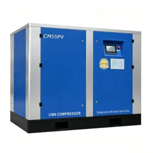
Description
CM/PV Series — Permanent Magnet Variable Frequency Water Lubricated Oil-Free Screw Air Compressor
7.5 kW – 320 kW · 0.8 / 1.0 / 1.25 MPa · FAD range 0.45–59.10 m³/min · ISO 8573-1 Class 0 · IPM motor + integrated VFD
The CM/PV series is the variable-speed variant of the CM/B water-lubricated platform. Everything that makes the CM/B attractive — Class 0 oil-free discharge, near-isothermal compression, stainless steel compression chamber — is preserved. What’s added is an integrated interior permanent magnet (IPM) motor and a factory-matched variable frequency drive (VFD), turning what was already a clean compressor into an energy-efficient one as well.
The practical implication is straightforward: if your process air demand fluctuates — as it does in the vast majority of industrial facilities — a permanent magnet variable frequency water lubricated oil-free screw air compressor will consume significantly less power than a fixed-speed equivalent running load/unload cycles. The VFD tracks the system pressure setpoint by continuously modulating motor speed, typically between 25% and 100% of rated speed. There is no unloaded running, no blow-off loss, and no pressure band hunting.
The series covers 17 frame sizes from CM08PV to CM320PV, with both air-cooled (F suffix) and water-cooled base configurations available up to CM160PV. From CM200PV upward, water-cooled only. Three nominal working pressures — 0.8, 1.0, and 1.25 MPa — are available on every frame, each with its own FAD range at variable speed.
CM/PV Series Technical Parameter Table
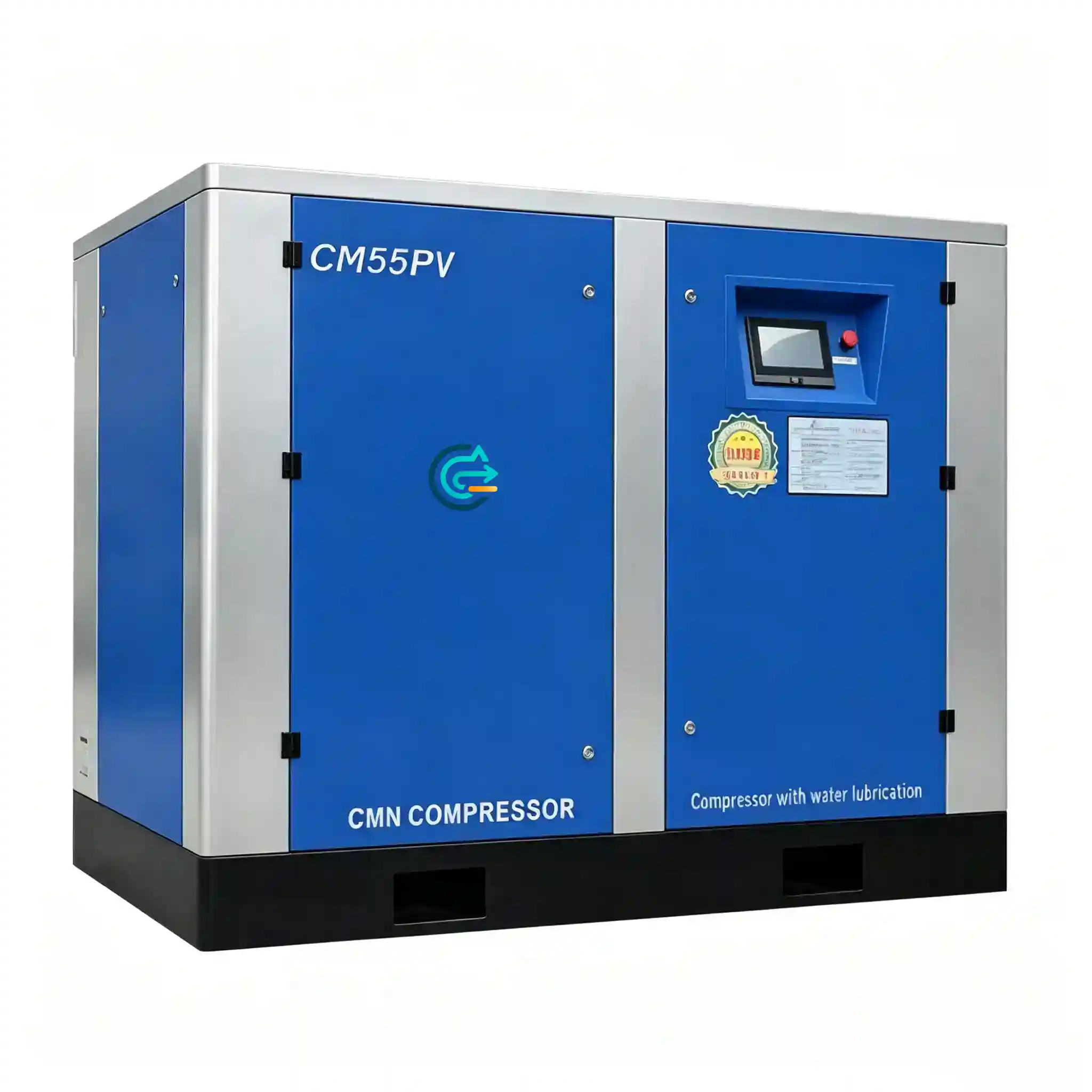
CM/PV series full parameter table · IPM motor + integrated VFD · 0.45–59.10 m³/min · 0.8 / 1.0 / 1.25 MPa
What the PM Motor and VFD Actually Change — Beyond the Brochure
A conventional induction motor runs at essentially fixed speed — slip varies slightly with load, but the compressor output is controlled by inlet valve modulation or load/unload switching, both of which waste energy. In the unloaded state, a fixed-speed compressor can still consume 25–35% of full-load power while delivering zero useful air. Over a year of three-shift operation, that adds up to a significant electricity bill for air you didn’t use.
The interior permanent magnet motor in the CM/PV eliminates the rotor copper losses of an induction motor. At partial speed — which is where a VFD-controlled compressor operates for much of its life — the IPM motor’s efficiency advantage over a standard IE3 induction motor grows: the IPM can maintain IE4 or better efficiency down to 25% of rated speed, where an induction motor’s efficiency degrades significantly. The result is that energy savings of 20–40% against a fixed-speed equivalent are genuinely achievable for variable-demand applications, not just in test-lab conditions.
Combined with water lubrication — which already delivers near-isothermal compression and discharge temperatures of ambient + 40–45 °C versus ambient + 80–100 °C for a dry oil-free machine — the CM/PV platform addresses the two main operational costs of industrial compressed air simultaneously: energy consumption and product contamination risk.
One additional point worth noting for procurement teams: because the VFD soft-starts the motor from zero speed, there is no inrush current spike at startup. This matters if your site has a weak grid connection or multiple large compressors on the same bus — the CM/PV will not cause voltage dip events that trip other equipment.
Series Performance at a Glance
Full Model Specifications — CM08PV to CM320PV
FAD values shown as a variable-speed range at each working pressure (minimum speed → maximum speed). All FAD values per ISO 1217 Annex C. Cooling water quantity based on inlet 32 °C. “F” suffix = air-cooled (风冷); base model = water-cooled (水冷).
CM08PV – CM37PV (7.5 kW – 37 kW)
| Model | Pressure MPa (PSI) |
FAD range m³/min |
FAD range cfm |
Power kW / HP |
Noise dB(A) |
Cooling T/h |
CW pipe DN |
Air outlet |
|---|---|---|---|---|---|---|---|---|
| CM08PV(F) | 0.8 (116) | 0.45 ~ 1.15 | 16 ~ 41 | 7.5 / 10 | 58 | 2 | DN25 | 1″ |
| 1.0 (145) | 0.41 ~ 1.02 | 14 ~ 36 | ||||||
| CM11PV(F) | 0.8 (116) | 0.62 ~ 1.55 | 22 ~ 55 | 11 / 15 | 58 | 2.5 | DN25 | 1″ |
| 1.0 (145) | 0.53 ~ 1.32 | 19 ~ 47 | ||||||
| 1.25 (181) | 0.48 ~ 1.02 | 17 ~ 36 | ||||||
| CM15PV(F) | 0.8 (116) | 0.96 ~ 2.40 | 34 ~ 85 | 15 / 20 | 63 | 3.5 | DN25 | 1″ |
| 1.0 (145) | 0.85 ~ 2.12 | 30 ~ 75 | ||||||
| 1.25 (181) | 0.64 ~ 1.61 | 23 ~ 57 | ||||||
| CM18PV(F) | 0.8 (116) | 1.24 ~ 3.10 | 44 ~ 109 | 18.5 / 25 | 65 | 4 | DN25 | 1″ |
| 1.0 (145) | 1.05 ~ 2.62 | 37 ~ 93 | ||||||
| 1.25 (181) | 0.85 ~ 2.13 | 30 ~ 75 | ||||||
| CM22PV(F) | 0.8 (116) | 1.40 ~ 3.50 | 49 ~ 124 | 22 / 30 | 65 | 5 | DN25 | 1″ |
| 1.0 (145) | 1.25 ~ 3.13 | 44 ~ 111 | ||||||
| 1.25 (181) | 1.04 ~ 2.61 | 37 ~ 92 | ||||||
| CM30PV(F) | 0.8 (116) | 2.00 ~ 5.00 | 71 ~ 177 | 30 / 40 | 66 | 7 | DN40 | 1-1/2″ |
| 1.0 (145) | 1.68 ~ 4.20 | 59 ~ 148 | ||||||
| 1.25 (181) | 1.52 ~ 3.18 | 54 ~ 112 | ||||||
| CM37PV(F) | 0.8 (116) | 2.44 ~ 6.10 | 86 ~ 215 | 37 / 50 | 67 | 9 | DN40 | 1-1/2″ |
| 1.0 (145) | 2.09 ~ 5.22 | 74 ~ 184 | ||||||
| 1.25 (181) | 1.92 ~ 4.81 | 68 ~ 170 |
CM45PV – CM110PV (45 kW – 110 kW)
| Model | Pressure MPa (PSI) |
FAD range m³/min |
FAD range cfm |
Power kW / HP |
Noise dB(A) |
Cooling T/h |
CW pipe DN |
Air outlet |
|---|---|---|---|---|---|---|---|---|
| CM45PV(F) | 0.8 (116) | 3.12 ~ 7.80 | 110 ~ 275 | 45 / 60 | 68 | 10 | DN40 | 2″ |
| 1.0 (145) | 2.45 ~ 6.13 | 87 ~ 216 | ||||||
| 1.25 (181) | 2.26 ~ 5.65 | 80 ~ 200 | ||||||
| CM55PV(F) | 0.8 (116) | 3.84 ~ 9.60 | 136 ~ 339 | 55 / 75 | 70 | 12 | DN40 | 2″ |
| 1.0 (145) | 3.44 ~ 8.60 | 121 ~ 304 | ||||||
| 1.25 (181) | 2.97 ~ 7.42 | 105 ~ 262 | ||||||
| CM75PV(F) | 0.8 (116) | 5.16 ~ 12.90 | 182 ~ 456 | 75 / 100 | 73 | 18 | DN40 | 2″ |
| 1.0 (145) | 4.57 ~ 11.42 | 161 ~ 403 | ||||||
| 1.25 (181) | 3.93 ~ 9.83 | 139 ~ 347 | ||||||
| CM90PV(F) | 0.8 (116) | 6.52 ~ 16.30 | 230 ~ 576 | 90 / 125 | 73 | 20 | DN40 | 2-1/2″ |
| 1.0 (145) | 5.81 ~ 14.52 | 205 ~ 513 | ||||||
| 1.25 (181) | 4.92 ~ 12.30 | 174 ~ 434 | ||||||
| CM110PV(F) | 0.8 (116) | 7.76 ~ 19.40 | 274 ~ 685 | 110 / 150 | 78 | 24 | DN40 | 2-1/2″ |
| 1.0 (145) | 6.76 ~ 16.90 | 239 ~ 597 | ||||||
| 1.25 (181) | 6.04 ~ 15.10 | 213 ~ 533 |
CM132PV – CM320PV (132 kW – 320 kW)
| Model | Pressure MPa (PSI) |
FAD range m³/min |
FAD range cfm |
Power kW / HP |
Noise dB(A) |
Cooling T/h |
CW pipe DN |
Air outlet |
|---|---|---|---|---|---|---|---|---|
| CM132PV | 0.8 (116) | 8.88 ~ 22.21 | 314 ~ 784 | 132 / 180 | 78 | 30 | DN50 | 2-1/2″ |
| 1.0 (145) | 8.15 ~ 20.38 | 288 ~ 720 | ||||||
| 1.25 (181) | 7.31 ~ 18.29 | 258 ~ 646 | ||||||
| CM160PV(F) | 0.8 (116) | 11.54 ~ 28.85 | 407 ~ 1019 | 160 / 220 | 78 | 35 | DN80 | DN100 |
| 1.0 (145) | 9.81 ~ 24.52 | 346 ~ 866 | ||||||
| 1.25 (181) | 8.87 ~ 22.17 | 313 ~ 783 | ||||||
| CM200PV | 0.8 (116) | 14.65 ~ 36.63 | 517 ~ 1293 | 200 / 270 | 78 | 43 | DN80 | DN100 |
| 1.0 (145) | 13.10 ~ 32.70 | 463 ~ 1155 | ||||||
| 1.25 (181) | 11.09 ~ 27.72 | 392 ~ 979 | ||||||
| CM250PV | 0.8 (116) | 17.15 ~ 42.88 | 606 ~ 1514 | 250 / 340 | 78 | 53 | DN80 | DN100 |
| 1.0 (145) | 15.60 ~ 39.00 | 551 ~ 1377 | ||||||
| 1.25 (181) | 13.87 ~ 34.64 | 490 ~ 1223 | ||||||
| CM320PV | 0.8 (116) | 23.64 ~ 59.10 | 835 ~ 2087 | 320 / 430 | 80 | 60 | DN100 | DN125 |
| 1.0 (145) | 21.40 ~ 53.50 | 756 ~ 1889 | ||||||
| 1.25 (181) | 19.30 ~ 48.25 | 681 ~ 1704 |
Note: FAD values for CM132PV are water-cooled only. CM200PV, CM250PV, CM320PV are water-cooled only — air-cooled configuration not available above 160 kW. Weight data for individual models: please request the full datasheet with dimensions (L×W×H in mm) from our engineering team.
Understanding the FAD Range — How Variable Speed Tracks Your Actual Demand
Every CM/PV model is rated with a FAD range rather than a single output figure, because the compressor’s actual delivery varies continuously with motor speed. Take the CM55PV(F) at 1.0 MPa as a concrete example: the VFD modulates output from 3.44 m³/min (minimum speed, 121 cfm) up to 8.60 m³/min (maximum speed, 304 cfm). At any point in that range, the machine runs at the exact speed needed to maintain your system pressure setpoint, with no blow-off and no unloaded idling.
This matters operationally in two scenarios that are common in B2B industrial environments. First, plants with large shift-to-shift demand swings — a food processing facility running a single bottling line on night shift versus three lines on day shift needs a machine that can efficiently cover that range without switching to a smaller unit. The CM55PV handles 40–100% of its rated output within the same skid. Second, plants with gradual demand growth — a variable speed water-injected compressor that’s correctly sized for current peak demand still operates efficiently at 60% of that when the plant is underutilised, rather than wasting energy running fixed-speed load/unload cycles.
The speed range ratio (minimum to maximum FAD) is approximately 40:100 across the series — a ratio of about 1:2.5. If your actual demand range exceeds this (say you need to cover from 15% to 100% of a given capacity), a fixed-speed base-load machine paired with a VFD trim machine is the more efficient architecture than a single oversized VFD unit. We can assist with that system-level sizing calculation.
One thing to watch when comparing PM VFD oil-free screw compressor specifications from different suppliers: some manufacturers quote maximum FAD as the rated performance figure and minimum FAD as a footnote. Make sure you’re comparing maximum-speed FAD to maximum-speed FAD, and that both figures are measured per ISO 1217.
Where the CM/PV Earns Its Place — Industry Applications

The combination of Class 0 oil-free air and variable-speed efficiency makes the CM/PV applicable across a wider range of regulated industries than a conventional VFD oil-injected machine. The industries below have a common characteristic: process air quality is non-negotiable, and energy costs are a significant operational budget line.
A permanent magnet VFD oil-free screw compressor for pharmaceutical manufacturing addresses two regulatory requirements simultaneously: ISO 8573-1 Class 0 for product contact air, and documented energy management for ESG reporting. GMP facilities typically have highly variable demand driven by batch scheduling — the CM/PV’s variable output avoids the energy penalty of running at fixed full capacity when only a portion of the production suite is active. Models from CM22PV to CM90PV cover the typical range for a mid-size pharma building.
Cleanroom process air demands are notoriously variable across the working day — tool cycling, wafer lot sizing, and maintenance windows all create significant flow variation. A fixed-speed oil-free machine handles this with load/unload cycling, which wastes 25–35% of motor power during the unloaded phase. The CM/PV eliminates that waste and maintains tighter pressure stability, which matters for pneumatic tool performance on sensitive process equipment.
In chemical plants, purging, catalyst handling, and pneumatic conveying loads vary significantly between batch cycles and continuous runs. A VFD compressor that tracks demand without overshooting pressure is also gentler on downstream pneumatic components — consistent pressure means longer valve and actuator service life. Oil-free operation matters for plants working with oxidising or reactive process streams where hydrocarbon contamination in instrument air could cause safety incidents.
Air-jet weaving looms and false-twist texturing machines are high-demand, high-availability applications. A weaving room running 120 looms around the clock has relatively stable air demand, but still benefits from variable speed during planned maintenance shutdowns when 30–50% of loom capacity is offline. Oil-free supply eliminates yarn contamination risk and removes the maintenance burden of coalescing and carbon filter systems.


The IPM Motor — Why It Matters More Than the VFD Alone
Some manufacturers fit a standard induction motor with a VFD and call it a variable frequency compressor. That’s not wrong, but it leaves efficiency on the table. An induction motor’s rotor copper losses increase at partial load because rotor slip increases, and overall motor efficiency drops — typically from 93–95% at full load to 88–91% at 50% load. If the compressor runs at partial load for 60% of its operating hours (which is common in real industrial demand profiles), that efficiency gap compounds over time.
The interior permanent magnet motor eliminates rotor copper losses entirely — the magnetic field is created by permanent magnets, not induced current. IPM motors maintain efficiency of 95–97% across the full speed range from 30% to 100% of rated speed. In a 55 kW installation running 6,000 hours per year at an average load of 65%, the IPM motor’s efficiency advantage over a standard IE3 induction motor can represent 5,000–8,000 kWh per year — roughly $500–$800 USD at typical industrial electricity prices, before accounting for the savings from eliminating unloaded idling.
The IPM rotor also has lower inertia than an induction motor rotor, which means the compressor responds faster to demand changes. Pressure overshoot during rapid load changes is reduced, which translates directly to more stable system pressure and less mechanical stress on the compression rotors.
A final practical point: because the IPM motor requires no external cooling air (the motor is cooled by the VFD’s thermal management system), the unit has no motor cooling fan that could pull contaminated or humid air across the motor windings. In coastal or high-humidity installations, this is a meaningful reliability advantage.
CM/PV vs CM/B — Fixed Speed or Variable? A Direct Comparison
Both series use the same water-lubricated compression stage with the same Class 0 discharge air quality. The difference is entirely in the drive system. Here’s the practical selection guidance:
| Criterion | CM/B (Fixed Speed) | CM/PV (PM VFD) |
|---|---|---|
| Demand profile | Stable, near-constant; < 15% variation | Variable; 15–60%+ swing between shifts |
| Motor technology | Standard induction, IE3 | IPM (permanent magnet), IE4+ efficiency |
| Part-load efficiency | Poor — load/unload cycle wastes 25–35% | Excellent — tracks demand continuously |
| Capital cost | Lower | Higher (VFD + IPM motor premium) |
| Payback period | N/A as baseline | Typically 1.5–3 years for variable demand profiles |
| Startup current | Star-delta; 5–7× FLA inrush | Soft VFD start; ≤ 1.1× FLA |
| Oil-free air quality | ISO 8573-1 Class 0 | ISO 8573-1 Class 0 — identical |
Rule of thumb: If your system runs at average utilisation below 80% of the compressor’s rated output for more than 4 hours per operating shift, the CM/PV will typically pay back its VFD premium within two years. At consistent utilisation above 90%, the CM/B fixed-speed machine delivers better ROI. If you’re unsure, share your demand log data (30-minute interval pressure/flow recordings if available) and we can run the numbers.
Footprint Reference — Air-Cooled vs Water-Cooled Dimensions
Dimensions shown as L × W × H in mm. Air-cooled units (F suffix) include the radiator fan section and are larger. Water-cooled units are more compact. All dimensions are for the standard canopy — open-frame configurations available on request.
| Model | Air-cooled (mm) | Water-cooled (mm) | Approx. weight (kg) |
|---|---|---|---|
| CM08PV(F) | 1550 × 775 × 1445 | 1350 × 774 × 1150 | 637 / 507 |
| CM11PV(F) | 1550 × 775 × 1445 | 1350 × 774 × 1150 | 657 / 527 |
| CM15PV(F) | 1900 × 1000 × 1635 | 1680 × 1000 × 1335 | 907 / 757 |
| CM18PV(F) | 1900 × 1000 × 1635 | 1680 × 1000 × 1335 | 993 / 743 |
| CM22PV(F) | 1900 × 1000 × 1635 | 1680 × 1000 × 1335 | 1023 / 873 |
| CM30PV(F) | 1950 × 1050 × 1780 | 1900 × 1050 × 1430 | 1200 / 1300 |
| CM37PV(F) | 1950 × 1050 × 1780 | 1900 × 1050 × 1430 | 1230 / 1320 |
| CM45PV(F) | 3040 × 1280 × 1800 | 1880 × 1260 × 1430 | 1930 / 1569 |
| CM55PV(F) | 3040 × 1280 × 1800 | 1880 × 1260 × 1430 | 2050 / 1665 |
| CM75PV(F) | 3040 × 1280 × 1800 | 1880 × 1260 × 1430 | 2270 / 1889 |
| CM90PV(F) | 3750 × 1850 × 2180 | 2500 × 1400 × 1580 | 3920 / 2356 |
| CM110PV(F) | 3750 × 1850 × 2180 | 2500 × 1400 × 1580 | 3950 / 2376 |
| CM132PV | Water-cooled only | 2500 × 1400 × 1580 | — / 2522 |
| CM160PV(F) | 4300 × 2000 × 2500 | 3100 × 1700 × 2090 | 5150 / 3810 |
| CM200PV | Water-cooled only | 3100 × 1700 × 2090 | — / 3910 |
| CM250PV | Water-cooled only | 3100 × 1700 × 2090 | — / 4120 |
| CM320PV | Water-cooled only | 3600 × 2800 × 2000 | — / 6350 |
Control System — What the PLC Manages and What You Can Integrate With
The CM/PV control package is more complex than a fixed-speed machine because the VFD, pressure feedback, and water quality monitoring all interact. The PLC manages:
- Pressure setpoint and VFD speed command: PID loop with configurable setpoint (±0.02 MPa typical pressure band). The VFD responds to frequency commands from the PLC — you set the target pressure, the system handles the rest.
- Discharge temperature monitoring: Thermocouple at the air-water separator outlet. High-temperature alarm and automatic shutdown protect the compression stage from overtemperature events.
- Water conductivity monitoring: Inline sensor in the compression water circuit. Alarm at ≥ 200 µS/cm; the system logs events. This is the most important predictive maintenance signal for water-lubricated machines — don’t ignore it.
- Motor current and power monitoring: Real-time kW draw displayed on screen; logged for energy reporting. Useful for verifying actual vs. expected energy savings after installation.
- Inlet air filter differential pressure: Differential pressure switch triggers a maintenance reminder before the filter becomes flow-restricting — important because a clogged inlet filter on a VFD machine causes the VFD to ramp up speed to compensate, masking the problem while reducing efficiency.
- Communication interfaces: Modbus RTU (RS-485) standard; Modbus TCP/IP optional. Allows integration into building management systems, SCADA, or IoT energy monitoring platforms. A 4–20 mA remote pressure setpoint input is available if your BMS provides the reference signal.
- Multi-unit sequencing: When two or more CM/PV units share a common header, the control system can operate in lead-lag mode — one machine handles base load, the second trims. This gives you redundancy and avoids the efficiency loss of running a single large machine at very low load.
Energy Saving — A Worked Example for CM55PV vs CM55B
This is a simplified but representative calculation for a common scenario. Adjust the figures for your own electricity tariff and actual demand profile.
Scenario: CM55PV(F) vs CM55B(F) — 55 kW, 1.0 MPa, air-cooled
- Operating hours per year: 6,000 h (three-shift operation, 250 days)
- Average demand profile: 40% of maximum FAD for 2,000 h; 70% for 2,500 h; 100% for 1,500 h
- Electricity price: $0.10 USD/kWh (adjust for your tariff)
| Load period | Hours | CM55B power draw | CM55PV power draw | Annual saving |
|---|---|---|---|---|
| 40% demand (partial load) | 2,000 h | ~40 kW (unload cycling) | ~22 kW (VFD modulated) | $3,600 |
| 70% demand (typical shift) | 2,500 h | ~52 kW | ~40 kW | $3,000 |
| 100% demand (peak) | 1,500 h | 55 kW | 55 kW | $0 |
| Total annual electricity saving | 6,000 h | ≈ $6,600 USD |
Indicative figures only. Actual savings depend on demand profile, local tariff, and operating conditions. Power draw estimates for the CM55B assume 75% loaded / 25% unloaded split at each load period, with unloaded power at ~35% of rated. CM55PV estimates assume IPM motor at IE4+ efficiency and cubic law fan affinity.
Technical Questions — Answered Directly
Get the Right CM/PV Configuration for Your Site
Tell us your required working pressure, approximate demand range (m³/min or cfm), site cooling type, ambient temperature, and annual operating hours — we’ll confirm the right frame size and payback estimate within one business day.